|
Yamaha's YEIS (Yamaha Energy Induction System), the first boost bottle  Yamaha invented the boost bottle system. On June 30, 1980, Yamaha announced a new engine system technology that it had developed independently: the Yamaha Energy Induction System (YEIS) for 2-stroke engines. YEIS was first used on the YZ motocross models in 1980, then on four other 2-stroke models in 1981. Here's the partial patent on the YEIS but the full paper will cost you $26. http://papers.sae.org/810923/ Boost Bottles sold for motorized bicycyles are mostly a scam because they aren't designed correctly. If designed correctly they can provide a power boost within a 2000 RPM band. When people say they got a power boost from one that is usually because their carb was providing too rich a fuel mixture at partial throttle opening which the boost bottle corrected. Maximum benefit can only be had on an engine with reed valve and expansion chamber because that kind of setup is what the boost bottle was engineered for. Read on to get the full story... Boost bottles act in two ways: 1. Within a band of 2000 RPM centered around their resonant RPM they serve to absorb and give back pressure. When the intake port or reed valve closes there is a pressure created by the sudden stopping of the fuel/air flow from the carb. Some of that pressure enters the boost bottle and then exits back in perfect harmony with the intake opening at the EIS systems resonant RPM. At all other RPM it does so with less force the farther away the RPM is from the systems resonance. The boost bottle acts like a Helmholtz Resonator with a reverberation frequency. Its center frequency depends on the size of the bottle and the inner diameter and length of the connecting tubing. 2. At RPM at or close to resonance it also acts to lessen the initial strength of intake vacuum at the carburetor as the flow from the bottle happens right as the reeds are opening. This lessens the initial surge of gasoline flow from the carb jets and so needs to be compensated for by enlarging the idle jet and lessening (lowering) the slide cutaway (by buying a slide with a smaller cutaway number if you don't know how to southern engineer it). Here's a graph from the YEIS patent that shows the canister pressure in harmony with the pressure/vacuum in the intake manifold (between the reeds and the carb). Each time the manifold pressure relaxes around zero, the canister pressure also goes towards zero. Every time the manifold pressure goes negative (vacuum) the canister pressure goes negative. I divided the canister pressure into blue and purple sections. The blue sections are a release of fuel/air charge into the manifold right when the engine creates a vacuum to suck in fuel/air charge. The purple sections are a storage of fuel/air charge from the manifold right when the reeds close. At this low RPM the manifold pressure doesn't maintain hardly any positive pressure. This only happens at higher RPM when the intake charge has enough velocity to cause a sustainable pressure every time the reeds close. 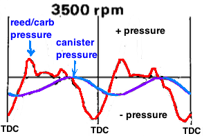 At the bottles resonant frequency it is the most efficient at giving and taking the fuel/air charge. That is it's "resonant RPM" although it will function in like manner 1000 RPM either side of its resonant RPM albiet with less efficiency the farther away the RPM is from the center RPM. I used an online calculator for Helmholtz resonators before I incorporated the formulas into my own calculator/spreadsheet. It turns out that designing them reveals that the volume of the canister is dependent on the volume of the connecting tubing and vice-versa when targeting a certain RPM. The more volume the tubing has the bigger the canister has to be in order to maintain the same resonant RPM. The YEIS patent showed (see graphic below) a dip in power when the pipes baffle wave returned to the crankcase just before BDC at 3500 RPM. I used my expansion chamber calculator to figure that the positioning of the baffle wave just before BDC happens right around 40% of the peak power RPM. So a bike that has peak power at 10,000 RPM will probably have a dip in power at 4000 RPM. Of course for a race bike that isn't important because keeping the bike in its upper 2000 RPM powerband means it won't be used at low revs except when crawling around in the race pits. But it would be important to trail and street bikes that use their full RPM range. But I don't recommend going by this 40% formula. Ride the bike at partial throttle with a RPM gauge and see for yourself when the torque trough happens. 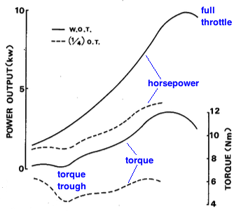 Why did Yamaha focus on synchronizing the YEIS to that torque trough? Couldn't it be designed to work at top RPM to boost peak power? No because the system has a dramatic result of changing the fuel/air ratio leaner for a band of 2000 RPM. It turns out the torque trough has a dramatically rich mixture due to the baffle wave causing the reeds to open later. When they open the piston has gained good upward velocity creating a strong vacuum and so the vacuum pulse through the reeds is pretty strong which causes a surge of gas through the jets. The YEIS can perfectly counter that occurrence. If it were tuned for another RPM range then it would make the mixture too lean there and the adjustment of jet sizes would affect the engines other RPM ranges next to it. By looking at the carb parts working range chart you'll see that the slide cutaway and the idle jet controls the mixture around 1/4 throttle open and can be changed to keep the mixture from becoming too lean (lean results in less throttle response). 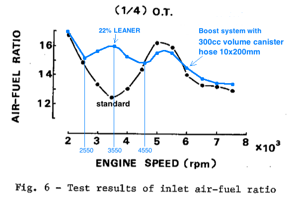 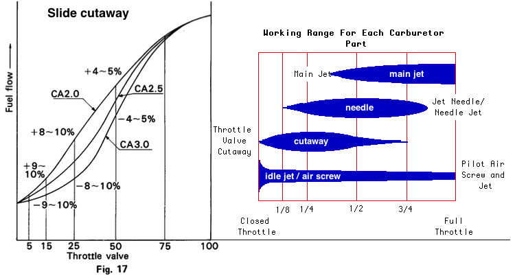 Also the steeper the baffle cone angle of the pipe, the stronger the baffle wave and the worse the power dip is so it's noticeable more with racing pipes than with street pipes. This dyno shows two power dips, one at 40% and one at 66% of peak power RPM. On the Yamaha IT200 the YEIS is designed to target the second dip in power, not the first one like they did in the patent. It worked out good for that bike with a resultant linear powerband.  patent notes: "The YEIS is one of the ideal mechanisms that permit improvements of performance and fuel economy in the low and medium speed, part throttle operation of the two-stroke engine." Pressure variation in the intake tract is more at low RPM than it is at high RPM, therefore the effect of the YEIS is much less at high RPM. Also it has more effect at partial throttle than at full throttle because the pressure variations in the intake manifold are more at partial throttle which activates the boxes ability to oscillate more. At 1/4 throttle the delivery ratio improved from 35% to 41%. At resonant RPM the YEIS improves the delivery ratio the most which improves engine power. Optimum conditions: When the YEIS resonant frequency is equal to the engine RPM where you want the most improvement. Canister volume should be more than the engine displacement. Minimum box size is 80% of engine displacement. Increasing the box volume (while maintaining its resonant RPM the same) to as much as 3x the engine size had no effect on performance. More than 3x was not tested. Here's a couple of graphs from the patent. There's a lot to be learned from studying them.  From the graphs it looks like at below half of the YEIS resonant RPM the power is the same or lower. So an EIS tuned to 6400 is only helpful above 3200 which is the case with the Yamaha IT200. 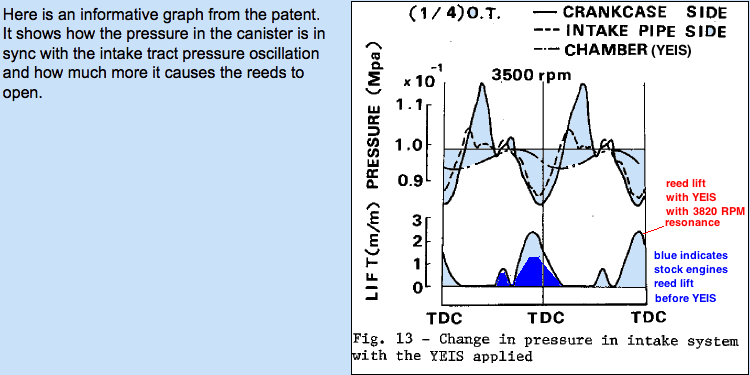 Here are the proper steps taken to design one: 1. Make the connecting tubing cross sectional area around 30% to 45% that of the cross sectional area of the carburetor. (Area = 3.14 x radius2) Yamaha tests showed that at 30% size the boost is 12% at 1/4 throttle, and 6% at 3/4 throttle. With 44% size the boost is 12% at 1/4 throttle and 8% at 3/4 throttle. 2. Estimate the needed length of tubing by the distance from the carb manifold to the imaginary (at this design stage) resonator box/cylinder which should be positioned so that any accumulated gasoline drains back down into the manifold. 3. Use my EIS Calculator and keep changing the theoretical canister volume till the resonant RPM is around the RPM of the engines dip in power. The canister volume should be at least the same as the engine size (ex: .000250 in my calculator is 250cc). Using 30% of the full throttle carb area for the cross sectional area of the tubing the following list shows what the maximum size carburetor is for each tubing size. 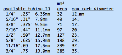 According to the Yamaha tests a boost bottle with 1/4" ID tubing on a reed valved engine with a 18mm carb only improves the delivery ratio (which directly relates to engine power) 1/12th what it would if the tubing was 3/8". The following patent test results reveal how important tubing size is. 13mm inner diameter (ID) is 30% the area of Yamaha's test carb and so the YEIS with 12mm ID gave much better results than that with 8mm at all test RPM. 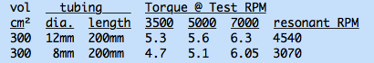 Here's a graph I made from the patent data which emphasizes one advantage of using tubing that is 44% the area of the carburetor. The improvement was in delivery ratio which pretty much equates to engine power. This comes from the original patent but then Yamaha used 30% on their motorcycles, not 44%, probably just for size limitation. 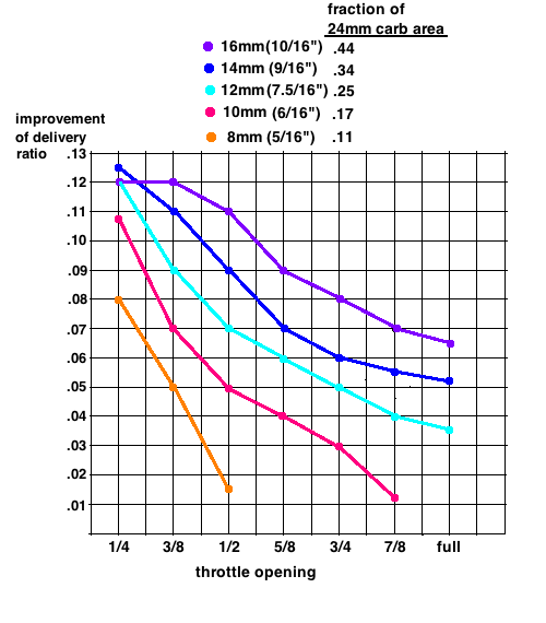 Myths: 1. The canister size has to equal engine size. Not so because the canister is not relating to the engine but to the flow and volume of moving intake charge from the carburetor. Its minimum size is the same as the size of the engine. The Yamaha IT200 has a 470cc canister. 2. It's OK to have a small tubing diameter to save space and cost. No, the tubing diameter needs to be in proportion to the carb size. Yamaha settled on 30% area for good reasons. 3. It's not such a great idea because if it were then all motorcycles would use it. First off it was patented by Yamaha which protected its use by Yamaha till '97. Since then Suzuki has patented their own similar system. I'm not sure what bikes still use it but the popular Yamaha RX115 and RX135 (2 stroke, reed valve) does. Almost no one except Yamaha or Suzuki engineers have known the rules for designing them or how to pick one for their engine which is why there have been more failures than successes. Since it helps very little at high RPM racing bikes don't have them. It is more for trail and street bikes. Also those people on small engines who are accustomed to only giving the throttle full twist (instead of gradually rolling it on in harmony with RPM increase) when they want to go won't notice any difference since it works best at partial throttle opening. 4. It doesn't matter how long the tubing is. Tubing length affects the resonant RPM of the system and so is very important. Also if the tubing is small then too long will prevent the wanted oscillation effect. My testing showed that 1/4" tubing shouldn't be longer than 3 inches, and 5/16" tubing no longer than 14". How does it work with engines without reed valve? Yamaha only tested it with a reed valve engine but I think it may also work with piston port intake engines, although with less effect. How they differ from engines with reed valves is that the intake vacuum pulse is always strong (evidenced by the strong intake noise coming from the carb) and so has a more linear fuel ratio to RPM graph so that there isn't just one or two little bands of RPM range that are too rich such as is with reed valve engines. What suggestions do you have for making a boost bottle? Below are the connectors and hoses you can match to your setup. Don't forget to buy the needed 18 pitch thread tap. Then drill and tap the manifold and bottle to accept the connectors. Use thread sealant to prevent air leaks. If your setup calls for nearly straight tubing then its best to use high pressure fuel tubing because it is resistant to gasoline. If you need a curved hose then use soft rubber tubing and check it every year for deterioration. Here are my recommendations of hose size and barb size to use with carburetors from 14mm to 36mm: 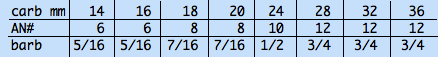 Here are sources for the barb hose connectors: 5/16" 7/16" 1/2" 3/4" High pressure fuel line (available at auto parts stores) is designated AN4 to AN12 and this list shows the percentage of full carb area that each tubing has for the listed carb sizes (12mm - 36mm). Since my bike has a 20mm carb I need to use AN8. 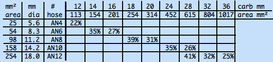 I think since this is a resonator/pressure-oscillator that it's important the connecting passageway to it has a smooth interior that is free from "steps" at the tubing connections. Just like the header of an exhaust pipe you don't want anything that creates interference patterns that would obstruct the flow. Make sure the hole inside the threaded part of the connectors is at least as large as the tubing inner diameter. If not then drill it out to the same inner diameter as the tubing. I got the idea that to function as a resonator there may be a limit to how skinny or how long the tubing can be. To test them I blew into the beginning of the tubing like I would into an empty Coke bottle to get a tune out of it. [see video] So I experimented with a 3.75" long 2.25" wide plastic bottle and with 1/4" inner diameter of tubing the maximum length was 3 inches. Longer than that and I couldn't get any reverberation sound when blowing across the end of the tubing. Of course that isn't final proof that a boost bottle won't function as a resonator if its 1/4" tubing is longer than 3" but it may be possible.  I then tested 5/16" ID tubing and it would reverberate up to 14 inches in length. I wonder if tubing length has been the unknown critical factor separating successes from failures. Boost bottles have been a "craze" in the motorized bicycling world but many people have said the boost bottles didn't work and many of the bottles come with long 1/4" ID tubings. There is one that uses a 5/16" ID tubing called Red Dog Boost Bottle. I like how it's angle of entry into the intake manifold isn't 90 degrees but is angled towards the intake port a bit which can only help. The area of 5/16" equals 32% of the open carb area of a 14mm carburetor. Here's the results of my computer analysis of the Red Dog whose seller told me the volume is 118cc and the tubing length 11". I added 1" to each listed tubing length due to the added lengths of the connectors. (i.e.: with the length of 15" I used 16" when calculating) to calculate their resonant RPM. tubing resonant
length RPM
15" 3313
13" 3531
11" 3805
9" 4155
7" 4623
The one from gas bike also uses a large diameter tubing but I don't know its cylinder volume. I don't recommend the BBR Boost Bottle from Bike Berry because it uses a 3/16" ID tubing which is too small.Or you can make one yourself. For around $20 you can have all the parts to make your own. For a 3000 RPM resonant frequency for an engine with a 14mm carb and 12" long tubing of 5/16" inner diameter all you need is a 6+10/16" long PVC pipe that's 1.5" inner diameter, and the two end caps and the glue, all at Lowes. Then find the 5/16" connectors and tubing on EBay. Check out this video of someone who made his own. For a 18mm carb you'll need 3/8" tubing 11" long and the pipe should be 2" diameter and 5" long. I analyzed a boost bottle for an '86 IT200 Yamaha and its boost bottle resonance was at 6400 RPM which boosts the range when normally the expansion chamber lowers the power right below the pipes power band. This bikes peak power RPM is 9500 and since a typical expansion chamber has a 2000 RPM power band then it may start at 7500. Here's how I calculate the bottles resonant frequency: resonant freq = 55.4 x sqr root of (tubings cross sectional area /(bottle volume x tubing length)) All distances, areas and volumes are in meters, squared meters and cubed meters. 55.4 is the factor to use for 100% humidity at 80 degrees Fahrenheit. 1.4 times the tubing radius is added to its length as a correction factor. The international Yamaha RX street models still use the YEIS and it is a popular bike in many poor countries. This is one example of many positive stories on the 'net: "I made my own Boost Bottle in the summer of 1981 for my '79 Honda CR 125R. It was made from 2" diameter aluminum tubing. On a lath I made an aluminum fitting for the intake manifold in front of the carb and behind the reed block. By 81 I was running a Mugen cylinder on the bike which was all top end power compared to the stock cylinder. I can honestly say my home made Boost Bottle improved the mid range power slightly. It was not a gimmick." Here's a video showing the boost bottle acts as a fuel/air reserve so that the throttle needs to have a smaller opening at idle. At the end of this video listen to how the bikes running too lean by how it takes too long to return back to idle after releasing the throttle. With the standard carb the needle should be at the second to lowest position. At the lowest position a boost bottle will make the idle mixture too lean. I made my own EIS for my Suzuki AX100 (with 20mm carb, expansion chamber, and reed valve) and it performed just as the patent said it would. My bike used to have a noticable dip in power before it came "on the pipe" at 5900 RPM but with the boost bottle it doesn't have that dip and now has a milder increase in power starting at 5200 RPM. Now it has more of a linear powerband and is doing better in street races. HOME |