Repairing or Replacing the KDX CDIHere is the info you need to repair your CDI (capacitive discharge ignition) but if you need a new replacement then I can sell you one. Click here to read about it. When
I owned the international version of the KDX200 (the SR) its CDI,
ignition coil, and stator coil all bit the dust after I failed to
tighten up the screws sufficiently on the stator plate upon reassembly.
A local technician replaced the SCR and rewound the stator coil, and I
bought (for temporary use) a generic ignition coil that has 1.5 ohms on
the primary. It worked but the spark was weaker. I've read that due to
moisture condensation it is common for the stator coil to lose good
contact with ground (chassis common), so it is important to keep those
contact places clean. I also imported a used CDI and ignition coil
(both not working. The coil primary only had .2 ohms whereas it should
have 1 ohm) from a normal KDX and I took the CDI apart and replaced its
SCR and then it worked. I didn't even know that these CDIs are
repairable but now I see that they utilize common components and no
type of brainy integrated circuit. So from my experience I want
everyone to know that CDIs can be repaired. The CDI from my KDX 200SR
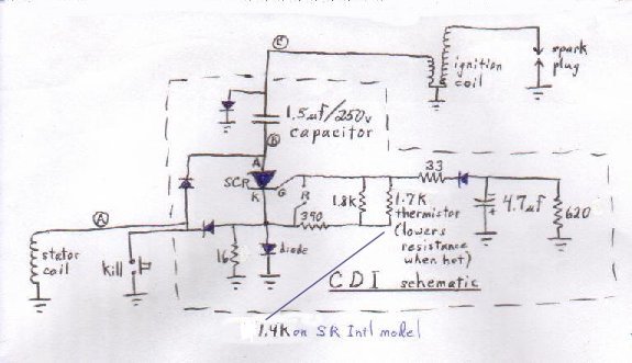
(Int'l model) is the same except for a 1.4K thermistor instead of a
1.7K thermistor that the normal KDX has. (the 1.4K retards the ignition
timing more).
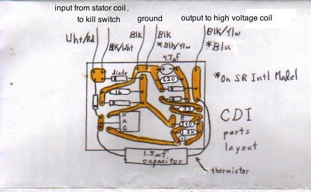
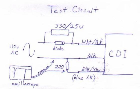
Wht/Red is the CDI input from the stator coil and Blk/Wht is the output to the kill switch. (The two CDI wires go to the same spot on the circuit and so are interchangeable.) The two black CDI wires are the ground wires, one from the magneto and one to the ignition coil. The Blk/Ylw wire is the CDI output wire to the ignition coil. The capacitor actually is unlabeled. A technician told me it is 1.5uf and then I put it in a circuit to test its value and verified that it is 1.5uf. This drawing shows the copper conductor paths as if you had X-ray vision. Actually they are on the back side of the board and unseen when looking at the parts side of the board. The part that has the letters K A G is the SCR. There is an unused space for a resistor to connect the gate (G) and cathode (K) which you would need to fill with a 12K resistor on the standard CDI if you replace the 1.7K thermistor with a 2K thermistor. The resistors are color coded and do not list numeric values. The codes are 16: brown/blue/black, 33: orange/orange/black, 390: orange/white/brown, 620: blue/red/brown, 1.8K: brown/grey/red. Recently I got an original CDI for a year 2000 KDX200 and here was its color coding for the wires: Wht/Red input wire, Blk/Wht to kill switch, Black is input ground, Blue is output, Blk/Ylw is output ground.
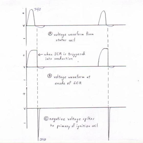
Circuit operation: The positive voltage from the stator coil charges the 1.5uf capacitor which remains high at the capacitor/SCR connection until the SCR turns on. This event happens when the cathode (K) of the SCR is sufficiently more negative than the gate (G). (when it reaches the required gate turn-on voltage, usually 2.5v). When that happens (a certain time period after the charge input changes from positive to negative) depends on the RC (not Ricky Carmichael. Resistor/Capacitor) time constant and the amount of negative voltage which depends on the stator coil and pull-down resistor (16 ohm in this case. if burned then the timing would be more advanced). The pull-down resistor is responsible for the negative half of the signal being so small (4 volts). Without it the negative amplitude would be 340 volts also. The sudden transition from +340v to -4v is translated across the 1.5uf capacitor to the primary of the ignition coil, which voltage is further amplified to deliver 10's of thousands of volts to the spark plug.
This test circuit doesn't allow the CDI to put out enough voltage to power an ignition coil, so you have to use an oscilloscope to view the voltage spikes coming out of it. If you don't use the resistor/diode input combo then you'll fry the 16 ohm resistor inside of it. The 330 and 220 are resistors. The 330 is a 25 watt resistor and much bigger than a normal resistor. It's now 2015, years after I made this page. Now I am farther down the rabbit hole and know from using my latest CDI tester that Kawasaki chose that 1.5uf capacitor for pre-'95 CDIs in order to keep the bike tame. That is because 1.5uf allows less voltage peak charge across it in this type of circuit. All the motocross CDI's use a 1uf capacitor because with higher voltage the final output voltage from the high voltage coil is more, resulting in easier starting and more spark power throughout the RPM range. So now I recommend this 1uf cap from Mouser for $2.69 and its number is 598-936C4W1K-F. Click here to read about how I modified the CDI for a different timing curve to better match my engine and pipe. More of my pages: SR mods, motocross mods, KIPS servicing, tire changing guide, alternative healing methods |