Understanding Return Wave Timings Via Horsepower Graphs
Here is a horsepower graph of a motocross engine with two
different expansion chambers.
One pipe has the baffle set too far back causing the "B" horsepower
peak to happen too late. The other pipe
had it set just right so that the "C" increase begins to happen right
at the end of the "A" peak. The pipe also
caused the "D" increase but that was probably due to less pipe
back-pressure which
makes the diffuser more effective. The B peak is 23% more RPM than the
A peak, and the C peak is 15% more.
So by this we know to never make the peak of the baffle wave occur at
EC at more than 15% more than
the engines natural
maximum RPM (dictated mostly by the exhaust port duration. Go by the
suggested max RPM on sheet 2
of ECcalc). The "crazy" graph can be corrected by lengthening either
the pipes header or the belly.
Here
is a graph of two engines with similar pipe timings so that the baffle
peak occurs before the natural maximum power peak. It causes a power
increase up to 8000 RPM. This fattens the
powerband
and is better for MX and enduro riding. The dotted line shows the
virtual power without the baffle return wave.

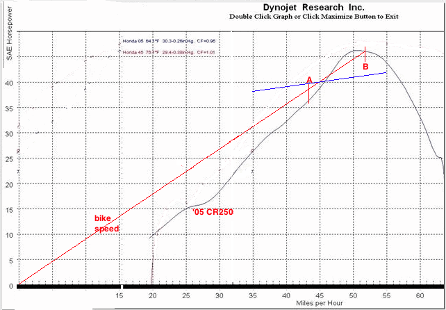
Here is a grpah showing the '05 CR250 as the under-dog to a bigger 4
stroke. Notice how it
peaks sharply. I think its baffle wave is timed to return at about 5%
more
RPM than its natural maximum RPM. That gives the best maximum peak
power but requires a closer ratio gearbox to keep the engine in that
top section of horsepower. That is what drag bikes and Grand Prix
racers like to have.
Now
with a red line drawn from zero which represents the linear increase of
rpm with speed we can see that the horsepower curve is out of
proportion. Ideally it should be equal to the blue line because only 2hp per each 10mph increase is needed due to wind drag and rolling resistance. Shifting RPM range is between A and B if the gear ratio is close
enough to have a difference of 1500 RPM from beginning of gear to end
of gear. To make this graph perfect the pipe needs to either shorten
the header or the belly, depending on the timing of the diffuser wave
in relation to the baffle wave. Either way that change will cause the
baffle wave to increase engine power at higher RPM and cause less of a
steep power incline.
Last but not least you need to consider piston size and its maximum
speed at max RPM. Most 250's shouldn't be designed for more than a max
peak power RPM of 8500 to insure normal piston life. (125's 11,000RPM. Click here for piston speed calculator. Don't go over 4000fpm.) So even though you
may be tempted to design a pipe for more peak power at higher RPM, you
really shouldn't do so unless you're prepared to change pistons more
often and to risk piston cracking. Either you need to time the baffle wave in sync
with the natural peak power RPM for the highest peak power possible, or
have the wave beefen up the power before that peak for a nice wide
powerband. Many bikes have pipes that give then the highest peak horsepower for bragging rights and "fun factor" but in the woods and motocross track it is wide powerbands that are most effective.
Here you can see the same 1500RPM powerband in red and a modified powerband in green. Although they have the same average horsepower, there is less variation in the green power curve. This is done by lengthening the header or belly. The blue curve is what I think would exist without any baffle return wave at all.
You can use the Excel file "KDX gear ratios" at http://www.visualize.co.nz/kdx200/
if you want to try to synchronize
the pipe powerband with the gear ratio spread. You just need to find out your bikes gear ratios (which you can do manually if you can't find that info on the internet). Click here
for an example of how I used it to figure out what to do for a Kawasaki
KDX 200.