|
Why I Don't Recommend Crank Stuffing Finding the Crankcase Compression Ratio 1. Remove the cylinder head and mark the crank (near the magneto) where the piston top is level with the transfer port top. Also, for a piston port engine mark it where the piston just closes the intake port. 2. Remove cylinder + piston + upper con-rod bearing and position the crank at TDC for a reed-valved engine, or at the degrees where the piston skirt closes the intake port of a PP engine. 3. Raise the bicycles front or rear wheel axle until cylinder/crankcase mating surface is level. 4. Pour oil or gasoline into the crankcase (at TDC for RV engines or at intake port closing for PP engines) up till its even with the cylinder/crankcase mating surface. 5. Use aquarium tubing to siphon out the liquid in the crankcase into a measuring cup. This is the TDC lower crankcase volume but if some of the cylinder walls extend into this space then you'll have to calculate those walls volume and subtract them from the total. 6. Measure the con-rods volume above the TDC position, measuring from a level equal to the cylinder mating surface to the top of the rod. 7. Turn the cylinder upside down and insert the piston (with pin + bearing) into it and move the piston to its TDC position for a RV engine, or to where the piston skirt closes the intake port for a PP engine. 8. Pour liquid into the piston bottom and the transfers until its at the bottom cylinder mating surface. 9. Pour that amount of liquid out into an empty measuring cup and note the volume. 10. Add the volume of steps 5 (crank) and 9 (piston/transfers), subtracting the volume of #6 (con-rod). This is the TDC crankcase volume. 11. Determine online (http://www.basic-mathematics.com/volume-of-a-cylinder-calculator.html) the volume of a cylinder with the length of your engines piston stroke till transfer opening as the "cylinder height" and the radius (1/2 diameter) of your cylinder bore. To be really accurate you'll need to subtract the volume the con-rod occupies for the same height. To do that you'll need to figure the equivalent cross sectional area of the rod as a cylinder by trial and error at http://math.about.com/library/blcirclecalculator.htm. Then use 1/2 that diameter (as the radius) and the piston stroke till transfer opening as the length of an equivalent cylinder and figure the volume. That will be the volume to subtract. 12. The volume of step 10 divided by the result of the step 11 volume subtracted from that of step 10 [ie: 10/(10-11)] gives the crankcase compression ratio.
The higher the number, the higher the peak crankcase pressure. (see chart below) A ratio of 1.5 means the expanded crank volume of "1.5" is compressed to "1". A ratio of 2 means a volume of "2" is compressed to "1". I have read that most MX engines have a ratio around 1.5 but that around 1.2 is better for low rpm power. Here's a graph showing the relationship between the crank ratio and the crank pressure: 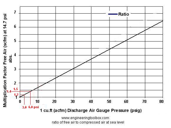 My 48cc piston port engine only has a ratio of 1.1 which gives about half the transfer pressure that a ratio of 1.2 gives. To change it to be 1.2 I need to reduce the crank volume by 80 square centimeters which you can come close to achieving by reducing the space by 60ml by filling the extra space to the left and right of the flywheel at the cases (use JBWeld). A 1.2 ratio yields 3psi transfer pressure while a 1.1 ratio yields 1.5psi. More space can be occupied by glueing aluminum plates to the insides of the flywheels but the glue (JBWeld) would insulate the aluminum from the hot flywheels and thus insulate the fuel/air from the same heat. The intake charge needs to be heated up so that the fuel atomizes and becomes more readily combustible. (see this site) On my crank I had also occupied 20ml space with JBWeld and aluminum plates on the inner flywheel sides for testing purposes. With my 48cc piston port top end it increased mid range and top rpm power but lost some low end power which I mostly regained by use of an intake extension (between intake manifold and carb). With my 55cc reed valved top end the ratio was increased from 1.2 to 1.4 (because reed valves cause a longer intake stroke than with a piston port top end). The results were a loss of power unfortunately but that may of been due to the transfer roofs angling upwards instead of being horizontal. The roof angle has to match the compression ratio. (With a reed valved engine how much space is between the intake port and the valve is of utmost importance. My home-made reed valve is installed inside the intake tract and so there is little free space there which allows much more crankcase ratio than if the valve was located back some. Measuring the space is essential to really know the ratio.) The increased pressure also caused the left side crankshaft seal to wear out faster. It is a very skinny seal and one of the weak links to this engine. I think it is still OK if you only have a piston port intake and a 1.2 ratio. But higher ratios with a reed valved intake may spell more maintenance. Luckily the seal only costs $4 and can be pryed out with a miniature screwdriver and the new one just banged back in. 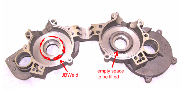 Here's how to stuff the crankcase space: Measure the inner diameter of the hollow circular area of the side of the crank (the fat weighty part). Place the crankcase halves on the floor so that their interior side is facing up. Cut a strip of aluminum (from a cheap bread pan) and make a circle of it of a diameter slightly less than that of the inner crank circle that was measured. Oil it so JBWeld won't stick too well to it. Place it around the crankcase area that is needed to be filled in. Mix up some JBWeld and fill in that area and let it set and dry for a day. Pull off the aluminum. Check to see if the crank touches any of the JBWeld and file/cut/dremel those spots down. Put it back together. (Get a crankcase gasket before starting and maybe also crank bearings and seals from pistonbikes.com. Get two of the skinny left seal since that seal wears out faster with increased crankcase pressure). Luckily it is easy to replace that seal in the future by removing the magneto and just prying it out with a jewelers screwdriver. Grease everything and just push the new one into place with your fingers. In the research paper "Some Development Aspects of Two-Stroke Cycle Motorcycle Engines" it is written that "the engine speed at which the maximum delivery ratio is obtained moves to a higher value in proportion to the square root of the crankcase volume". So I figured that reducing the volume from 200ml to 140ml increases the peak rpm by 1500. Primary compression from http://www.lortim.demon.co.uk/vsih/crankcas.htm Modern short stroke water cooled engines that employ large transfer port areas do not require a high primary compression ratio, in fact a high primary compression ratio substantially increases the pumping losses and decreases the power available. However, this does not apply to the long stroke of the Villiers unit that uses small transfer ports, even though pumping losses do increase there is a net increase in power. For road racing a minimum geometric primary compression ratio of 1.4:1 is required, 1.5:1 would be better but it is difficult to achieve without extreme measures. The higher ratio is used to squirt the charge through the narrow port. The speed of the charge entering the cylinder is further enhanced by the narrowing of the port, its inlet area should be at least 150% larger than its outlet. A good primary compression will improve tractability and performance whether for road or off-road riding, don't allow this pressure to be diluted through the use of a hollow gudgeon [piston] pin. Modern engines should be considered as having transfers fulfilling a "store and forward" function for the fuel with the real control being exercised by the exhaust. The modern exhaust shape required easy access to a supply of fuel mixture, exactly what the large transfer system supplies. What a modern system cannot do is sustain a long deep draw of fuel from the crankcase through inadequate transfer passages. In the long stroke small transfer engines, there is significant advantage to be gained from the truly explosive entry of the compressed gases from the crankcase into the cylinder, sweeping the remaining exhaust gases out into the exhaust port in a manner described by Schnurle many years ago. As the piston descends and before the transfer ports are uncovered, a hollow gudgeon pin will bleed off some of the primary pressure that you have fought to create. The hollow pins should be plugged with an alloy slug or slugs which should have no more than a 1 thou clearance fit and be coated with Loctite or similar. Interference fits will swell the gudgeon pin causing fitment problems. The lack of interference fit is required to allow the Locktite to key and bond, a zero or interference fit will not allow the Locktite to work properly. At racing speeds, the difference in power can be measured on the dynamometer. The geometric primary compression ratio (GPCR) is useful in determining whether crankcase stuffers are necessary. Be under no illusion: good primary compression is important. If your GPCR is less than 1.2 then action is definitely required.
|