|
First you can use sheet 1 of ECcalc to get ballpark figures for the right lengths of header, diffuser, and belly so that after fine tuning with header and belly lengths on sheet 3 the combined return waves shown will sync with the port timing at the middle of the powerband like what you see here. Make the return waves horizontally positioned so that at 1,000 RPM below the top powerband RPM the peak of the baffle wave will be about 5/7th (70%) of the way from TC to EC. 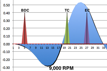 Here is sheet 1 where you will enter the basic engine data. Data entry boxes are in light blue. This section is also useful when porting an engine and trying to decide on the exhaust and transfer duration. Row 6 continues at row 19, row 7 at row 20, etc. The basic design steps are listed at the bottom right. To the left of it you can get an idea of what exhaust pulse duration (width) you should use. Getting this exactly right is impossible without the expensive pressure trace equipment that race teams use but you can get close. Anyway the difference between a 1ms and 1.2ms pulse is only a 14% width difference in the return diffuser wave. Sheet 1 can calculate for a pipe with any exhaust pulse duration but sheet 3 can only graph the return waves within a certain range of exhaust pulse durations. There are 3 versions of ECcalc. Use ECcalc12 for durations between .75ms and 1ms, ECcalc12b for 1.1ms to 1.4ms, and ECcalc12c for 1.5 to 1.8ms. The biggest effect of the exhaust duration is how much the diffuser and baffle waves overlap, so if you hate not knowing how close our guesstimate is then just make the belly adjustable in length. By trial and error you can get the best power and powerband once you get the correct wave overlap.  Enter exhaust port duration* at A6, transfer port duration at B6, top of powerband RPM at C6 (not the over-rev RPM but the top of the meaty part of the powerband which is 2000-2500 RPM wide depending on the length of the baffle), exhaust pulse width at D10, inside-of-header temperature at D14, at D15 how many millimeters from the piston the thermocouple was located in the header, and at F14 the RPM at which the temperature was taken. (Without knowing the temp just put in these temps for these exhaust port durations; 575° C for 165° exhaust, 600° for 180° exh, 625° for 190° exh, 650° for 200° exh. Also make the thermocouple distance half that of the header length [and recorrect after changing the header length later], and make the test RPM the same as your RPM at C6). Take notice of the blowdown time at E6. A good target blowdown is .5ms if you are porting it. (* the "duration" refers to how many crank degress the port is open each crank revolution)  Now set the baffle length according to how much "hit" you want (at the sacrifice of powerband width and with more power loss just before the powerband. read more). A normal range is 150-240mm. Then set the belly so that the values at J19 and L10 are very close. The right belly length is that which lets the diffuser and baffle waves to cross over each other just enough to shorten the diffuser wave a bit.  Set the diffuser length at B19 (at least 160mm. read more). Double check your diffuser design on sheet 2. If you can't get all the % area changes to be less than 15% then make it of multiple cones or lengthen the diffuser till you can. Then set the header length so the values at M12 and M14 match. If this is a new design without an exhaust temperature measurement then in order to maintain the same intended mid-header temperature at F19 you will need to reset the thermocouple distance at D15 to half the length of the header after you change the header length. Then adjust the header length again if the values at M12 and M14 don't match. 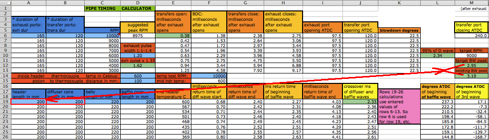 Unfortunately this last step of matching M12 to M14 only works with single coned baffles. If you have a multi-coned baffle design then complete the steps as normal and then on sheet 3 adjust the header length so that at 1000 RPM below the peak of powerband RPM the peak of the baffle wave (on the combined waves graph) is 70% from TC to EC. Then enter all the data for the power graph and if it needs to be adjusted left or right then do so with the header length. The following info only pertains to bikes that have more than a 2000 RPM spread between gears (such as 4 speed bikes). The baffle length determines what the RPM range of the powerband is so you need to know what the RPM spread is between gear changes on your bike. On sheet 4 you can see the gear/RPM calculator. First you need to know the rear wheel circumference (length around it). Position the wheel so that the valve stem is low center. Mark the ground at that same point. Sit on the bike and roll forward till the valve stem is again at lowest position. Measure that distance on the ground. If you measure in inches then put that number in K14 and then put the number from L14 in H14. Next find out how many crank revolutions per rear wheel revolution your bike has for each gear. Put the bike on a center stand so that the rear wheel is off the ground. Remove the magneto cover and make a mark on the magneto and on the cases. Remove the spark plug(s). Rotate the rear wheel 1 revolution and count how many crank revolutions there are. Put those numbers in H20-25. Put the powerband top RPM in H13. L21-25 will show the RPM range for each gear if you upshift when the bike reaches to top RPM of the powerband. Use the largest of those numbers from gear 3 on up as your target powerband. In this example it is 2000 unless you want to not be so precise in your shifting or want some power when lower than the pipe powerband. In this case a single coned baffle should suffice.  Next Page |