| Here's a view of most of sheet 1 where you will enter the engine/pipe/RPM data. Data entry cells are in light blue. The heading for each explains its purpose and if you hover the mouse over the cells with a red corner in their top right then extra comments will appear explaining in more detail. Here I have circled where you need to enter data. 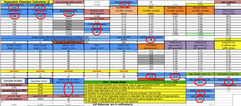 If you move sheet 1 over to the left you will see more data cells that need to be filled. Notice the flared header degrees (from centerline) at I33. Typical is around 1.5 degrees. The larger the end of header diameter at I31, the larger the angle. 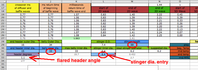 First you should analyze your current set-up and find out what your top RPM is just by using this program. In addition to the data you entered in accordance with the above step you need to also enter the pipe section lengths at A19 to E19. The measurement for the straight header begins at the piston face and ends where the flared header starts. Guess at the top RPM and enter it at C5 and after entering it if I15 is lower than H2 then raise the RPM at C5. If I15 is higher than H2 then lower the RPM. Knowing your top RPM gives you a reference point for possible pipe changes for a different top RPM. 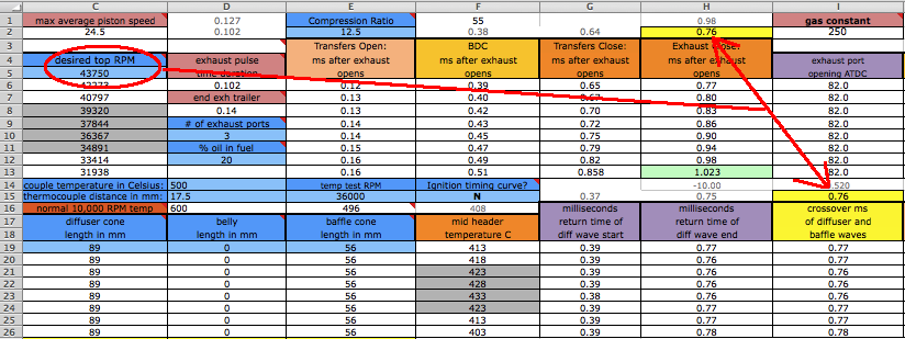 Next you can get close to finding out the percentage of total RPM the pipe powerband occupies. Select each of C32 to C35, one at a time, and write down the numbers displayed at H13 and K27. Whichever of those 4 selections produce the closest numbers indicates the closest % pipe powerband (displayed next to the X at B32 to B35). 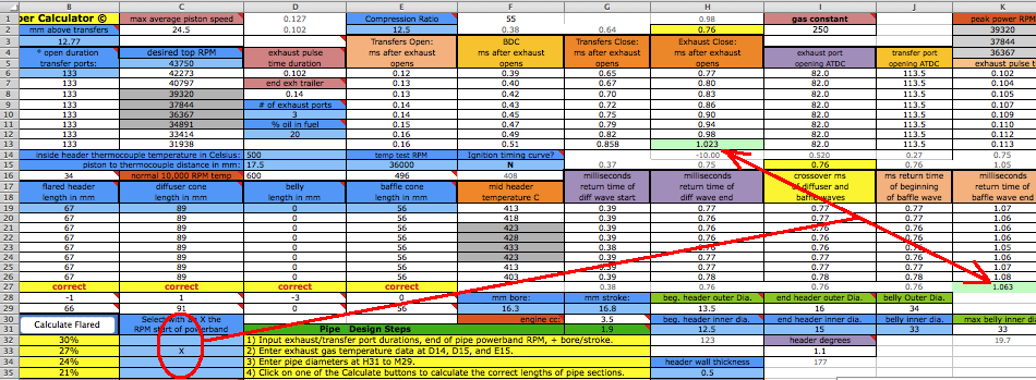 Possible Pipe Changes: You can lower the top RPM by lengthening the header or belly or raise the top RPM by shortening them. You can lower the amount of pipe "hit" and increase the over-rev by lengthening the belly but if you don't also shorten the header/diffuser by the same amount then that lowers the top RPM. You can lower the hit with a longer baffle cone (the rear cone) with a less steep angle. This also increases the RPM range of the powerband. If you want a different top RPM then enter it at C5 and then make the changes to the pipe section lengths till H2 and I15 match. If you want a different % powerband then choose one of the four available with an X and then change the baffle length according to E29. Enter that E29 value at E19 and the numbers at H13 and K27 should nearly match. Or if you want to design a pipe from scratch then continue with the following steps: Notice the recommended belly width at K31. You can enter it at J31 or enter a smaller diameter to fit any limited spacing for the pipe. The ideal stinger inner diameter is recommended at M31 and the closest avilable size from Metals Depot is listed at N31. Choose what size you will use (which can differ from these two options) and put it at L32. 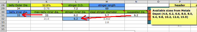 After entering the top RPM at C5 you will need to select the % of the pipe powerband at C32 to C35. Put an x besides the % displayed at B32 to B35 that you want. After doing so the percentage that the pipe powerband occupies from the total RPM is displayed at A33. 25% is most typical. More than that gives less peak power and less than that gives more peak power. 20% to 30% is the typical min/max range in my experience of pipe building. I wouldn't go outside of that. Notice how the beginning pipe powerband RPM at C13 changes with different percentages. After clicking the Calculate button if the baffle is too long (E19) for the given space then select a lower percentage and reclick the Calculate button. 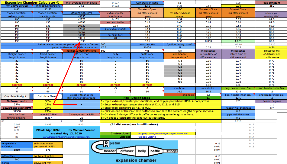 These 3 circled numbers concerning exhaust gas temperature are usually good to use with fuel of 80% methane and 20% castor oil. If you have measured data then you can change them. The best way to know if the temperature is right for your setup is by knowing the top RPM of your engine, then enter all the engine and pipe details and if H2 and I15 aren't the same then keep changing the temperature till the #'s match. Then you can design a new pipe using that temperature. 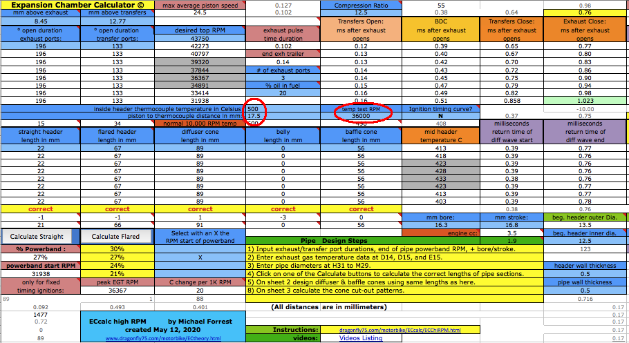 After entering all the other data then click on the Calculate Straight button if your pipe only has a straight (non-flared) header, or the Calculate Flared button if your pipe has a flared header. Flared headers are the best for high RPM engines. But first you need to enter the length from the piston face to the beginning of the flared header at A19. 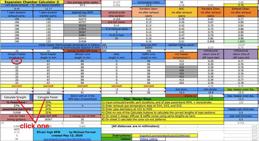 These are the calculated distances for each pipe section. If you want a different header or diffuser length then you can manually change them but keep the same added total length of header and diffuser the same. Don't worry that the belly is often zero. Because the timing between port openings is much shorter than on a motorcycle engine then the diffuser and baffle waves need to overlap more by lessening the belly length. 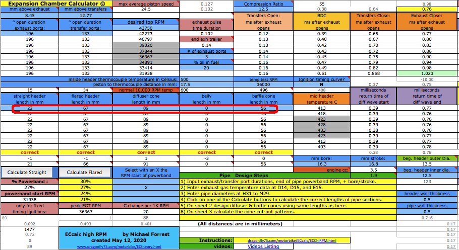 Sheet 2 takes the data from sheet 1 and uses it to calculate the cone angles for a single cone diffuser and baffle. But there are manual diffuser and baffle cone angles calculators on this sheet if you have any need of them. For a motorcycle design the program shows that an increasing angle baffle gives some power boost so that may be something you may want to try if you are desperate for whatever small gains are possible. Unless your engine has a reed valve then nothing more than a single cone diffuser is needed. A 3 cone will give some power boost when there is a reed valve. 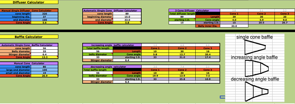 Sheet 3 takes the data from sheet 2 to display the measurements you need to use with poster paper to make the cutout pattern for each cone. It is very helpful to have a long metal ruler. The results are displayed on row 35 for a single cone diffuser. On row 39 is how to make a single cone baffle. Rows 40 to 42 are for an increasing angle baffle of 3 cones. If you want to do it manually then enter the data at rows 26 to 31. 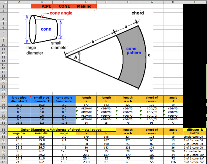 Click here for full instructions on using the Gear Ratio Calculator. If has the ability to handle 6 gears so in your case just use the row for 1st gear. You can use the same method for finding out the gear ratio if you have a mini race car and then all you need is the top speed to find out its top RPM. This is the section of sheet 3 that displays the final pipe specs and the engine and powerband details. 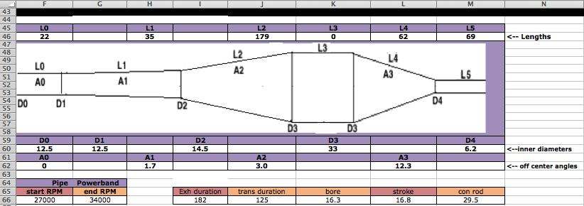 |