 Look at the bottom left of sheet 1 to see the 4 sheet tabs. You go to the desired sheet by clicking on its tab. The design steps are listed on sheet 1. 
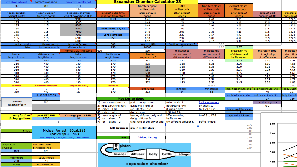 At D6 you need to enter an exhaust pulse time duration from the graph near the bottom of the sheet. For example, for a multi exhaust port 250cc you can see the time is .72 milliseconds. Getting this exactly right is impossible without the expensive pressure trace equipment that race teams use but you can get close here. That duration affects the time span of each of the the two pipe primary return waves. Anyway the difference between a .8ms and .9ms exhaust pulse is only a 5% width difference in the return diffuser wave so this calculators approximation is good enough. 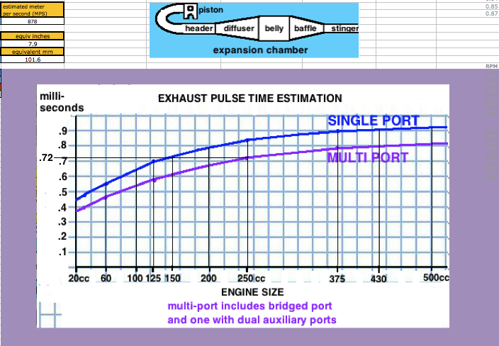 [In the following screenshots I often border the input cells in red that I'm talking about.] You'll need to know either the exhaust/transfers port durations or their distance from top of cylinder minus "deck" to the top of each port. Then use an online port duration and piston height calculator to find either the durations or the heights. Enter the port durations (read how to measure) and end RPM of the pipe powerband (at the end of being "on the pipe" which is usually about 750 RPM above peak power RPM) at C6. The RPM you enter at C6 should not exceed a 25meter/second piston speed on this calculator and a warning will display at D3 when it exceeds that. When entering RPM do not type in the comma. For example enter 9000 instead of 9,000. The port "duration" refers to how many crank degress the port is open each crank revolution. It's best to determine them by using an online calculator and the port heights (instead of using a degree wheel which is inaccurate because it's hard to see when the top edge of the piston is level with the top edge of the port). 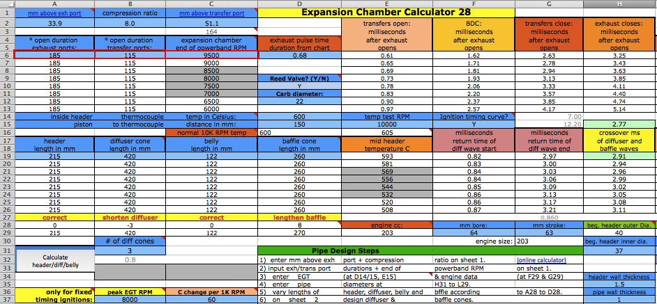 The RPM you enter at C6 corresponds to the very end of the pipe powerband, beyond where you would normally upshift. The graph below shows the end of pipe powwrband at 6750 RPM but most people would shift around 6600 RPM, just a few hundred RPM past the peak power. This example is for a 250cc motocross bike. Much longer powerbands are possible so it's best to just listen to the pipe and use that along with feeling the power to pinpoint the end of your pipe powerband. Then you can choose to stick with that or go a bit lower or higher. 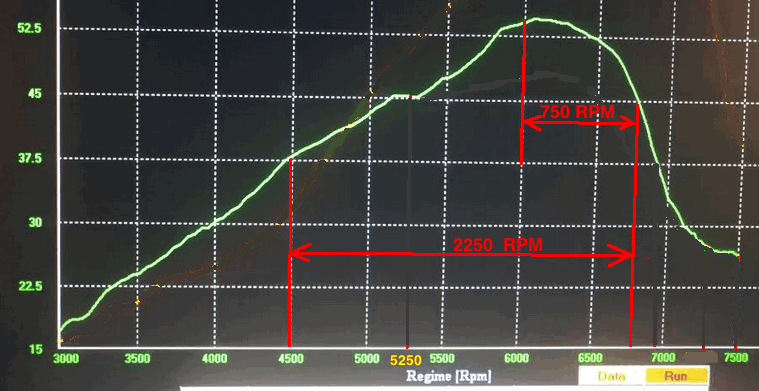 At D10 enter "Y" (for yes) if your engine has a reed valve intake or "N" if it doesn't. At F15 enter "Y" if your ignition system varies the ignition timing with RPM (like any normal modern CDI does), or "N" (for no) if it has fixed timing ignition (such as was on all old bikes such as the old Husqvarna and Maico motocross bikes). 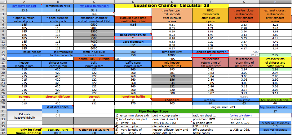 Enter the exhaust gas temperature in Celsius at D14, distance from piston to thermocouple at D15, and RPM at test temp at F14. If you don't know what it is then just use 600 at 10,000 RPM at 150mm. The best way to know the exhaust gas temp without measuring it is to ride the bike with a speedometer on it (which can be a bicycle speedometer) and note the speed when the bike is at peak power. Then use the gear ratio calculator to figure out at what RPM that happened. Then fill in all of sheet 1, 2 + 4 and on sheet 3 click the Auto-Graph button at H185 to see the peak power RPM. Then keep adjusting the temperature at sheet 1 D14 and clicking the Auto-Graph button till the peak power is at that RPM. Enter the engine bore and stroke at F29 and G29.  How to use the Gear RPM Range Calculator: Go to sheet 3 and scroll down below the pipe power grapher to see the Gear RPM Range Calculator. A) Measure your rear wheels outer circumference: Push the bike till the valve stem is at the very bottom. Mark the ground next to the tire equal to where the stem is. Sit on the bike and roll forward till the stem is once again at the very bottom. Mark the ground there and measure the distance between the marks. If you measured in inches then put that value at J231 to know the equivalent distance in meters at K231. Enter the wheel circumference meters at G231. B) If you leave G229 blank then this calculator will use the end of pipe powerband RPM from sheet 1. Otherwise it will use whatever RPM you enter there. C) Put the bike in 1st gear. Take off your ignition cover and prop the bike up so the rear wheel is off the ground. Take the spark plug out. Spin the wheel till the valve stem is at a spot that you can easily remember (such as visually at the top edge of the swingarm.) Mark the flywheel and the cases so the two marks align. Slowly turn the rear wheel while counting the complete turns of the flywheel. Do this till the valve stem returns to its original position. A sloppier but easier way is to hold a pencil in the spark plug hole and count the times the piston hits it. Write down the crank rotations per wheel rotation and put that number for each gear from G237 to G242. D) Take note of the RPM spread in the K column of 2nd gear. Your pipes powerband should be at least that wide. To find out the RPM for a certain bike speed (KPH or MPH) just keep entering different RPM at G229 till the right speed is listed for the right gear. (the speed in a certain gear you experienced)  Enter the stinger inner diameter. Choose between the ideal size at M31 and the available prefabricated size listed at N31. Look at the comment hidden at N30 to see common available inner pipe diameters for use as stingers (from Metals Depot): 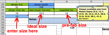 Enter the pipe inner diameters at H31 to J31. Enter the metal thicknesses at H35 and H37. All these dimensions are important to figuring out the approximate gas temperature inside the pipe which affects wave speed. The temperature decrease along the pipe is calculated by the outer area as the "dissipator" of heat. The max belly diameter at K31 is not a strict value but it's a good average max.  Click the Calculate button for the right pipe section lengths to be entered into A19 to C19. If you need the header to be longer or shorter than what is calculated then just enter the desired length at A19 and then make up the difference at B19. Example: to increase the header length by 50mm you need to decrease the diffuser length by 50mm. Header length here includes the distance from the piston face to the beginning of the pipe. 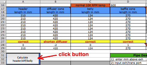 On sheet 2 you can let the sheet automatically create the diffuser dimensions or you can manually enter your own. Just put an x at F39 for it to automatically calculate for you a diffuser. Then select at G45 to G47 what type of diffuser you want. The beginning diameter and angle for the 1st cone are at C46 and C47. For the 2nd cone at D46 and D47, and for the 3rd cone at E46 and E47, and those are all transferred to a section to the right where they will be transferred to sheet 3 to be used in the creation of the diffuser return wave. If you want to change the total diffuser length, beginning diameter, or belly diameter then do so at sheet 1. If the desired diffuser length exceeds the range of 80mm to 440mm then you have to put an x at F40 and do it all manually.  For manual diffuser creation of a 3 cone diffuser outside of the range of 80mm to 440mm you can still use the values created in the mini calculator. First make sure the space at F39 is blank and then enter an "x" at F40. Then enter the three diffuser angles into C7, C17, and C27.  Then enter the two beginning cone diameters from D47 and E47 to B17 and B27. The mini calculator says the first cone is 30mm long, the second 20mm, and the third 20mm. So then enter the first 3 pressure change #s from row 12 to the M column for the first cone. Then the first two change #s from row 22 to column M. Then the first two change #s from row 32 to column M. Make sure all other cells in the M and N column have 0 in them.  Or you can use the cone calculator at B37 to B40 to design your own diffuser one cone at a time. Here's a look at what the diffuser waves look like with the 3 diffuser designs.  Now we can calculate the baffle cone. Usually a single cone is good. Compared to a 260mm long cone a 100mm cone gives about 20% more pipe power (not total power) but reduces the powerband about 600 RPM. For street and enduro bikes you will probably want less pipe boost and a wider powerband. For that you can make the baffle up to 300mm long. The automatic option for the baffle is different than for the diffuser. For it just click on one of the 5 baffle length calculators and everything will be done for you, including having the same baffle length entered on sheet 1. If you didn't OK the use of macros when you first opened the spreadsheet then you'll have to save it (to not lose the data you already entered), close it, and reopen it and enable macros. If you go much over the recommended belly diameter then you should try the decreasing angle baffle.  If you want to manually create a baffle then use the manual calculator. In this example I'm going to make a 200mm long one of two cones. I used the mini calculator to figure out the angle for the first cone after entering its beginning and ending diameter. Then I put that angle at A56. Then the resultant pressure change #'s were entered in column M.  Then for the second cone calculation I made the beginning diameter the same as the first cones end diameter and for its end diameter I made it the same as the stinger outer diameter from sheet 1 (inner diameter + 2 x wall thickness). Then I entered the calculated cone angle from B94 into A65. Then I entered the resultant pressure change #'s into column M folowing the previous five numbers. If the baffle were to be longer than 200mm then I would leave the third sections diameter (at A72) and the third sections angle (A74) blank so that section can be a continuation of the second section.  Pipe Power Calculator
The whole point is to have the best pipe powerband (graphed power height and width). After entering the estimated peak horsepower at I186 just click onto the Auto-Graph button and the calculations will display the resultant pipe powerband below the return waves graph. 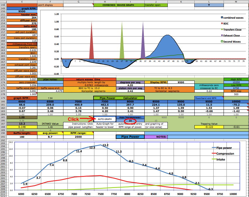 Power Factors: The intake is determined mostly by the average height of the diffuser wave, how much of the time it occupies between BDC and TC, and the pressure at TC (negative is best). The compression is determined by the pressure at TC, EC, and slightly before EC. Those two graphs are added together for the resultant power. 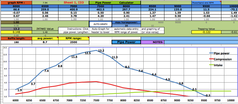 Trying Variations: It is good to record the results of the current pipe design and then try a couple variations and record each ones result. In this example I shortened the belly by 40mm and the power increased but it shortened the powerband a bit. (You can't create energy, just move it around). You can change the diffuser length on sheet 1 to move the powerband up or down on the RPM scale. And changing the belly length will change the powerband shape a bit. If you add 20mm to the belly then subtract the same amount from the diffuser. If you've selected manual diffuser design on sheet 2 then you need to re-do it there after any diffuser length changes on sheet 1. 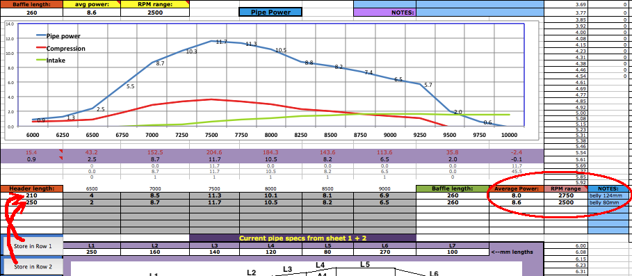 With your pipe design finished you can go to sheeet 4 to know how to cut out the patterns from poster paper which you can then trace onto the sheet metal (.7mm or more thickness) before cutting it with tin snips. You'll need an extra long ruler. This sample pipes data has been entered in the cone making section below for you to see how its done.  Every diameter needs the sheet metal thickness added to it which is done for you at A38 to C41. Just enter those values into the light blue cells above that section if your design has a 3 cone diffuser and single cone baffle. For any other design then just ignore A38 to C41 and make sure you add in the sheet metal thickness to all the pipe diameters you enter starting at A29. After entering the data in the blue cells then use the calculated data at D29 to H34 to draw the graphics pattern on poster paper. The gray area of the graphic is the pattern to be cut out, laid on sheet metal, and traced around with a felt marker so you can cut out the cone section with your tin snips. Each of the 6 rows (29-34) are for a separate cone.  You can also use the Cone Layout software from this site which has the added advantage of making the cutout patterns for more complex designs. Questions & Answers What is the most import guideline for designing a diffuser? Make it 3 cones if it's for a reed valve engine. It makes a big difference. What if the available space for the belly is less than the recommended belly diameter? Just make do with the available space. But the wider the belly the more power it will contribute. What if I design a pipe with a belly diameter greater than the recommended max? No problem but as you go much beyond it then you may need to use a decreasing angle baffle. What happens if my design varies from the suggested lengths on sheet 1? I encourage every one to experiment with variations from what is recommended to get the absolute best power. But usually what is recommended is very close to ideal. What if the recommended pipe section lengths on sheet 1 are impossible for the space available on my bike? Well then you'll have to change the lengths to match the bike. Bike designers have always had that problem. If the designed pipe is longer than the available space then consider raising the end of pipe powerband RPM so the design will be shorter. On my bike I had to use a 2 cone diffuser design due to space limitations. Can I just make the diffuser a single cone? Yes but it won't have an ideal 'delayed' wave peak which is needed for optimal power. Maximum effort at making a great pipe is essential if you want the best power. Don't be lazy and take shortcuts. What recommendations can you give for designing a pipe for a bike for a beginning rider? For a beginner you might want a pipe that gives as little "hit" as possible. You can do that by making the belly width smaller, the belly longer (and the diffuser shorter), and the baffle longer. Also you can design for the end of the pipe powerband to be about 1000 RPM below the normal end. It would make it more grunty like a trail bike. Also you can replace the base gasket with glue and add a head gasket, all to lower porting for less peak RPM. What can I do to get more pipe boost? If your pipe powerband is longer than what you want or need then you can shorten the baffle with steeper angles for a stronger but shorter return wave. Keep in mind that the wider the belly is the stronger the cone angles will be for the same cone length. Bigger angles mean stronger return waves. Also a 3 cone diffuser is very advantageous. Is there any advantage to a 1 degree flaring header? Yes if you can have a belly at the maximum width recommended or even more in order to keep decent angles of the diffuser cones. Dynos have proven that doing that produces more power. |