|
Learning by Experimenting My Suzuki AX100 has a 3000 RPM spread between gear shifts because it has only 4 gears. Its original expansion chamber was a diffuser, belly, and silencer (instead of baffle cone). It worked good when new with a linear powerband and acceleration equal to 200cc four strokes. But as time goes on it got slower because a small hole in the silencer gets smaller as carbon deposits accumulate. So at 7400 km I decided to upgrade it with a true expansion chamber and silencer, both of my own design. But at the time I didn't know how to see from my Excel file ECcalc (expansion chamber calculator) what the RPM range of the pipe powerband would be. So I designed the pipe below and built it from .7mm thick sheet steel. I had previously measured the exhaust gas temperature at 670 degrees Celsius at 10,300 RPM and seen that there was a 33 degree drop for every 1000 RPM drop. The new pipe gave extra kick from 65-80kph in 3rd, and the effective part of the new pipe powerband was 7300-8900 RPM. The baffle graph strength at EC was .34 to .42 at these RPM. That is only a 1600 RPM powerband and I had to rev it to its absolute maximum before upshifting for it to be in the beginning of the powerband and continue to accelerate. So I knew that design was a failure.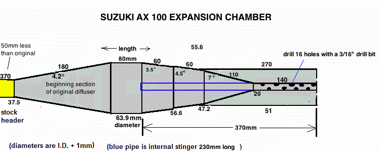 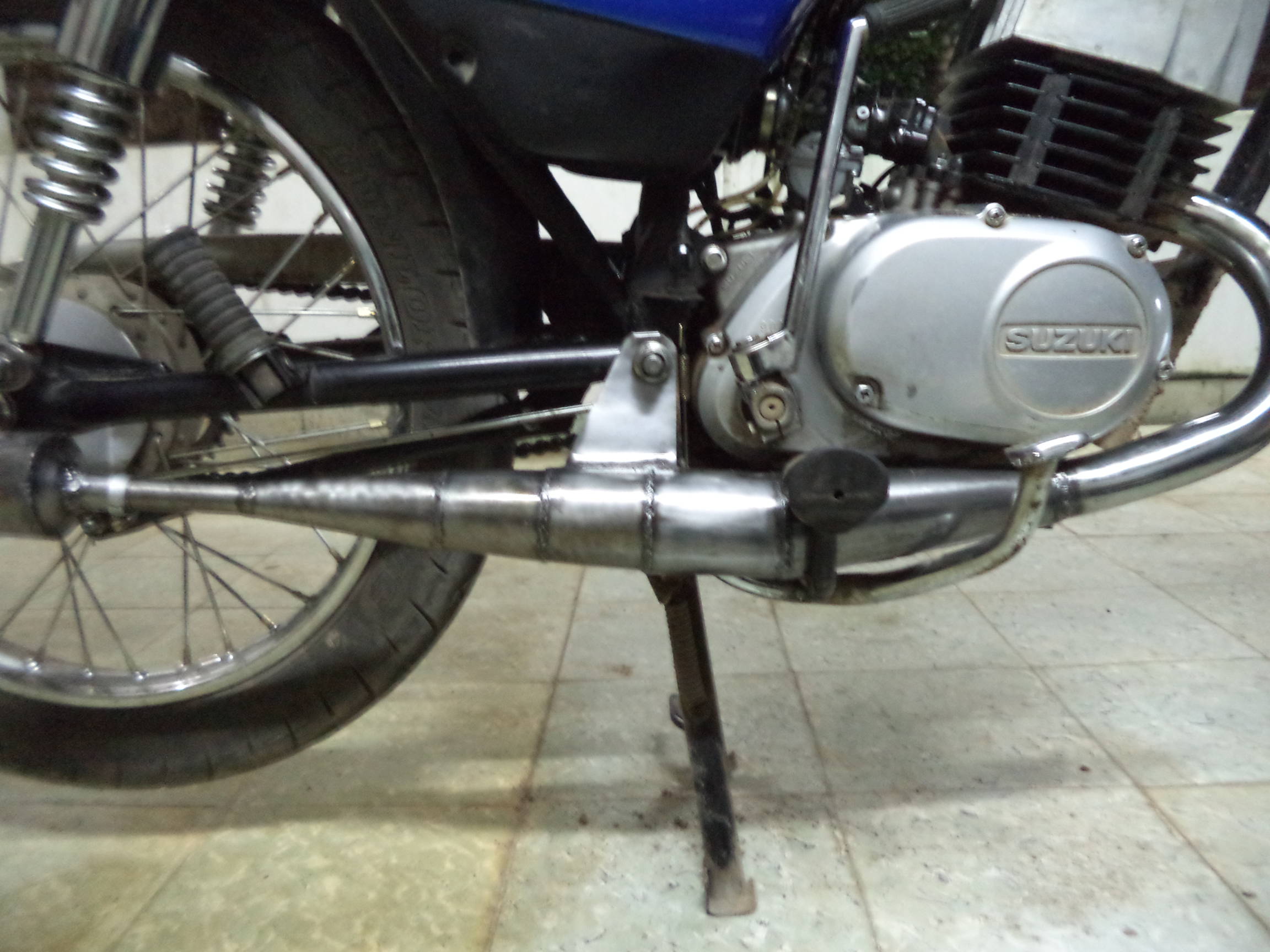 Here are its return waves graphs: 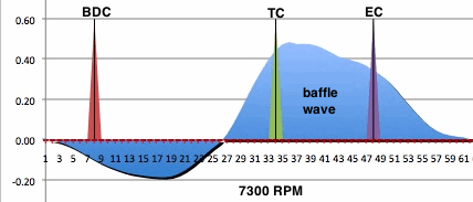 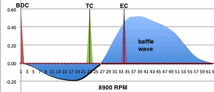 Then I redesigned the pipe by adding two baffle extenders and replacing the final cone for one with a slighter angle. Here is the design, picture of the real pipe, and its return waves graphs: 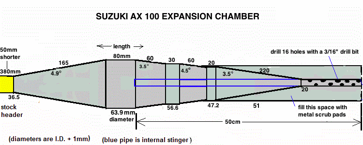 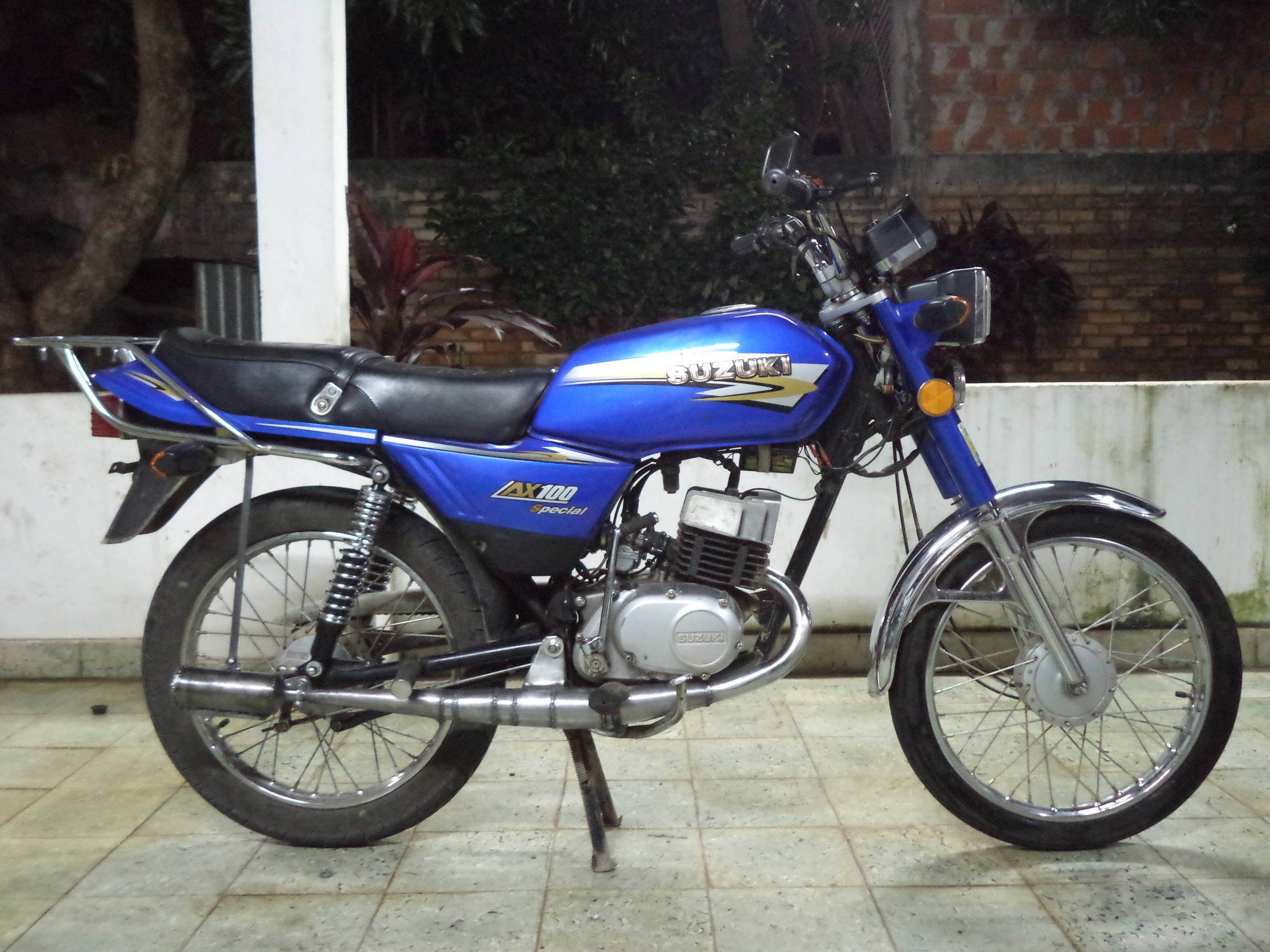 Here are its return waves graphs: 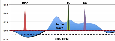 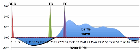 It only worked so-so with a 2200 RPM powerband which kept me from being able to use 4th gear because it lost speed once I upshifted to 4th due to not enough power at the lower RPM. What is obvious now is that I can't say every pipes powerband can be determined only by the baffle wave strength at EC. which is what I thought just before this test. The second pipe had lesser baffle wave strength at both ends of its powerband which was proof that pipe power is not just by the baffle wave. So I put my thinking cap on and finally came up with a formula that figures the powerband based on the wave strength at TC and EC and some other factors. I kept adjusting the formula till it jived exactly with what my experience was with these two pipes which were very different in their baffle waves. With that calculator I figured a
new design that allowed almost no belly length, allowing the new pipe
to have steeper
diffuser angles, a stronger diffuser wave, and a stronger baffle wave
which allowed a wider wave for a wider powerband. I put it together and
tested it. The performance was good until I shifted into highest gear.
If the head temperature was more than 295 degrees F then it couldn't
keep accelerating. Now I see why Suzuki made their pipe the way they
did, because it's very hard (and impossible without the right
calculator) to design a pipe for such a broad powerband. Here is its
design and graph of its return waves at top RPM:    Here is its graph at 8500 RPM:  The result was just as I predicted with more power in the lower part of its powerband as a result of the right upward sloping baffle wave. Now it can accelerate in 4th gear, but power still drops off above 295 degrees. This engine has a heat problem due to 3 factors: 1) I live in a hot South American country, 2) engine compression is higher than it was stock due to a higher compression ratio and the supercharging of the expansion chamber, 3) the engine is air cooled. Ideally it needs a cylinder head with a squish band. If it becomes too much of a problem then I'll need to lower the compression ratio. |