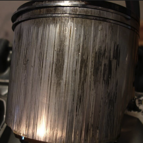
| Holing the Baffle Cone Some karts used this trick. Supposed to give better power below the pipe powerband and extend the over-rev. The holes greatly diminish the baffle wave to keep it from interfering with the intake when at RPM below the pipe powerband. The graph on the left is from one of Blair's papers showing the over-rev, slightly less peak power, and lack of pre-powerband power dip.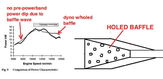 I think it allows more over-rev by disallowing 3rd generation waves. Usually the 3rd generation baffle wave returns to the cylinder at high RPM between BDC and transfer closing which interferes with intake. (most people are unaware that 2nd, 3rd, 4th generation waves are generated) This shows why the baffle wave is just as troublesome as it is beneficial. With a 178 exhaust duration it is countering the diffuser wave all thru the pipe powerband. With a 190 duration it counters the diffuser wave just the first half of the pipe powerband. So with a 190 duration the baffle wave lessens beginning power and increases ending power. I got these return wave graphs using my pipe calculator software. I think all street and trail bikes should have holed baffles. And all race bikes should have at least 190* exhaust duration. 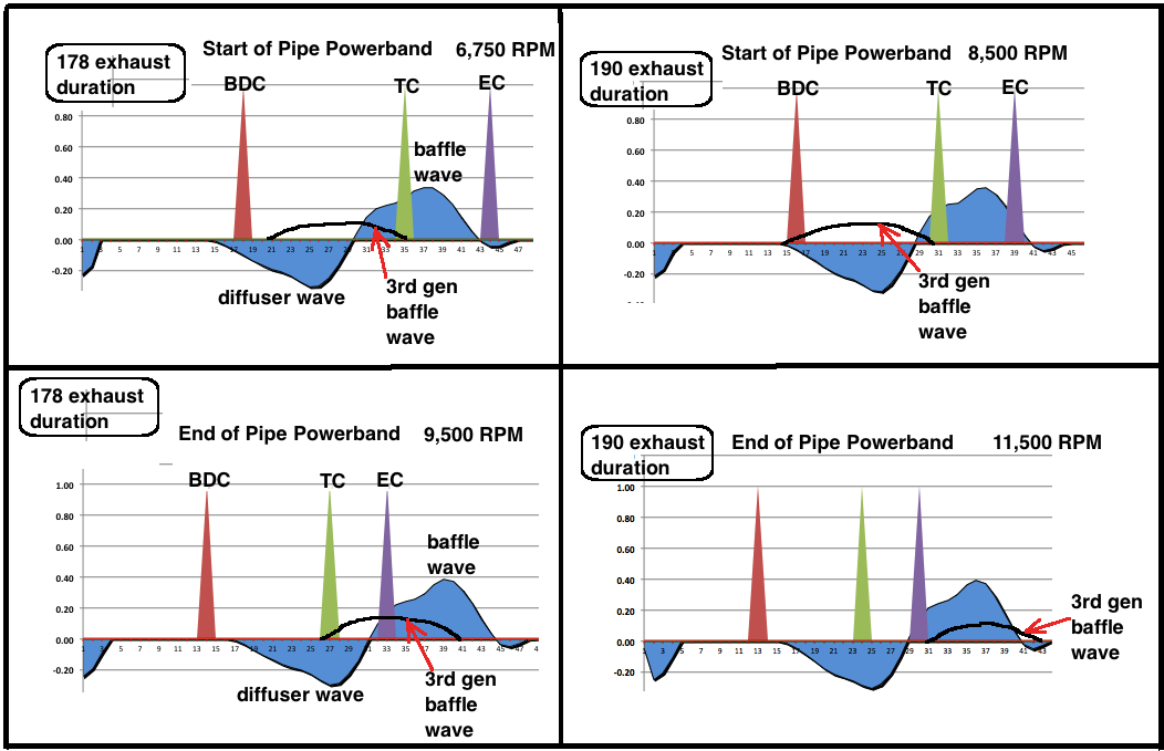 You can make multiple rows of holes like this : 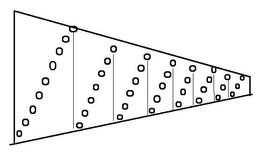 Here's the IAME 100CC karting engine exhaust pipe:  Pipe Belly Stinger Having the stinger entrance start in the belly area avoids having the sound wave compressed like it is at the end of the baffle cone. If it is sized right then there is no change in power and the exhaust sound is half as noisey. It is the entrance into outside air and the sudden relief of pressure that causes the exhaust bark. The less the initial pressure, the less the bark. When Steve Buffel at BRC Engineering was consulting with me for pipe design on one of his new engine projects he wrote me: "Placing the stinger in the belly had no negative effects on power! This was a nice surprise :) " The only possible negative effect is increased engine heat if you don't use a larger diameter stinger pipe due to the increased length. Increasing the length increases the back pressure if the diameter isn't increased. If you care about public opinion about motorcycles then you care about noise levels. 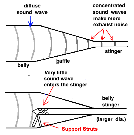
Do the Pipes Return Waves Push/Pull Mixture? The return baffle wave is of positive pressure and at peak power RPM the rising piston is closing off the port just as the positive pressure from the wave ramps up to match the rising piston trying to squeeze out mixture from the cylinder into the pipe. If the pipes rising pressure from the wave matches the "possible" rising pressure from the piston (if the port wasn't open) then no charge is lost to the pipe. Proof that the return baffle wave doesn't push back hardly any mixture into the cylinder comes from the % increase of power which verifies that mostly what happens is that the mixture is kept from escaping into the pipe (at peak power RPM. Before and after that RPM some mixture does escape). The return diffuser wave does pull some mixture into the cylinder if the cylinder pressure momentarily becomes less than the crankcase pressure. But at peak power RPM its action is also similar to the baffle waves in that it causes a loss of cylinder pressure that somewhat matches the "possible" loss of crankcase pressure as the piston is rising in order to prevent mixture or spent gases from being sucked down into the crankcase. What complicates this scenario more is the presence of the reed valve (if there is one). It opens up and lets more intake charge in due to the low cylinder pressure the return wave causes which affects the crankcase pressure. This intake of mixture increases the delivery ratio which increases engine power. Sound waves move air molecules laterally (a little bit) only while they are in the wave. After the wave passes they return very close to their original position. Here's some important on-line quotes: "there's really no sideways movement" https://van.physics.illinois.edu/qa/listing.php?id=14771 "They [the air molecules] return to roughly their original position" https://physics.stackexchange.com/.../how-sound-waves-and... "The forward motion of a tine [sound wave] pushes air molecules horizontally to the right and the backward retraction of the tine creates a low-pressure area allowing the air particles to move back to the left." https://www.physicsclassroom.com/Class/sound/U11L1c.html But while a pressure or vacuum wave (of substantial duration) increases or decreases the air pressure in one area that has connection to the next area (such as thru the partially open exhaust port) then there can be air flow from the higher pressure area to the lower pressure area because although the wave enters the cylinder, it's effect of changing the pressure inside the cylinder is weakened due to the greater cross sectional area of the cylinder. Best Racing Pipe Design If you have an engine with transfers that aren't close to the exhaust and you have a single cone diffuser then you can get a significant power boost from modifying it to have an increasing angle diffuser. I found that out with my AX100 that just had two transfers (total). 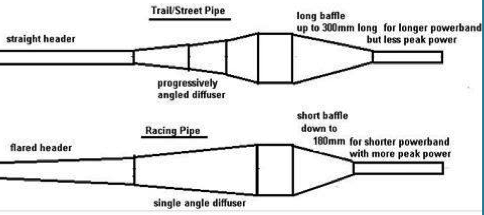 I think the best design of diffuser for all engines is an increasing angle design with at least 3 cones. It's best because it causes the return wave peak to happen near the end of the wave which is best to have the wave peak happen near transfers closing at peak power RPM. A single cone diffuser has its wave peak near the beginning of the wave which isn't good. But the diffuser angles have to be lessened for a race bike with transfers close to the exhaust port to lessen the wave peak for less loss of intake charge out the exhaust port. Race engines can lose mixture out thru the exhaust port more easily because their velocity of mixture going thru the transfers is less due to the large total transfer area. Engines with less transfer area have higher flow velocity which is less likely to be influenced by the return vacuum wave. 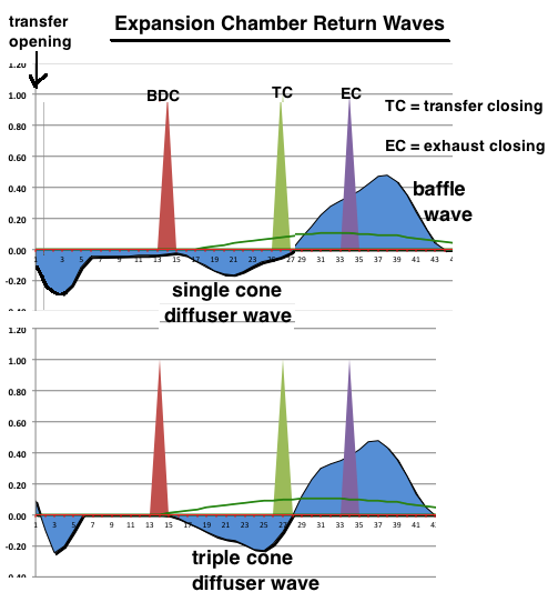 Early expansion chambers were just headers and diffusers, no belly, no baffle, and no silencer. It's the multi-stage diffuser with increasing angles that creates the best shape of diffuser wave that gives the best results. But with engines that have two transfer ports very close to the exhaust port it may be too much and intake charge is lost out the pipe due to that closeness. Probably that's why pipes for them usually have single angle diffusers that minimize the effect of the diffuser wave. Also they often have expanding headers which cause the diffusers to have even less angle and become less effective. So engines with less ample porting are the ones that mostly benefit from multi-cone increasing-angle diffusers. The engines with very ample transfer porting get less benefit from the pipe but get more power emphasis at high RPM which is why race engines need that design. The more transfer area there is, the more power at high RPM, even without a strong return diffuser wave. Smaller diffuser angles are had when designing/modifying a pipe with the presence of an expanding header which then makes the beginning of the diffuser a larger diameter which gives less room for big angles (since you don't want to make the belly too wide). But the typical header angle (from centerline) is 1* to 2* which leaves too little diffuser angle which causes a too weak diffuser wave to much aid the cylinder intake. I prefer to have a 3/4* angle as a compromise. Conclusion This is what I would prefer to do for a race bike with ample transfer porting. I would reduce the header angle to 3/4*, and make a 3 cone increasing angle diffuser to put its peak at the right location (near transfer closing). That way the peak strength is moderate and the timing of its peak is better. 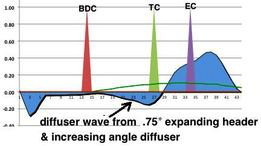 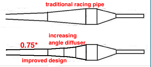 Rounded Exhaust Port Top In Italy Max Quattrini got 30% more power from a scooter engine by changing cylinder design to improve the flow of all ports using a flow bench to analyze changes. One of those changes to improve exhaust port flow was to round off the top of the port. Max explained that the exhaust port timing must be taken from when the port really starts to flow, and not from when the piston edge first opens the port window. In this case it is much like the small decompression drillings above the exhaust port on kits like his M210TV and the SST from Casa Performance. You do not take the exhaust timings from when these little drillings open as they are too small to really affect the flow. According to some other tuners in Italy, this radiused port shape is not unique in the world of 2-stroke tuning, but it is certainly unique in the world of production scooter kits. It took Max's foundry and the plating company several goes to get exactly the right mould dimensions and thickness of plating to make the port shape exactly as per his design in Solidworks. Improving the exhaust flow makes the port more efficient which should result in top RPM power gains without having to raise the port as much. SOURCE 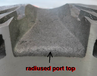 I think he also changed the port dimensions to not let the port bottom be all the way down to BDC which reduces loss of intake charge out the exhaust port. Look at how rectangular the exhaust port is and the "transition hump" at the bottom. 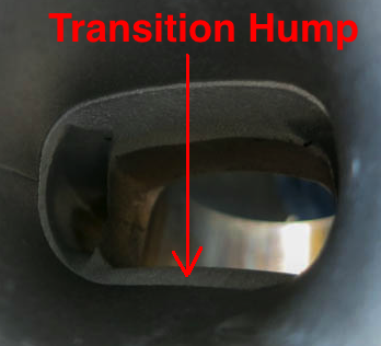 Too Little Engine Oil Amsoil Interceptor is a good example of a low viscosity oil that needs plenty of it added to gas in order to have enough protection (like 25:1). It also shouldn't be used in high performance engines since it has little or no synthetic oil in it. Synthetic and castor protects cylinder and bearings up to higher temps. Amsoil Dominator is what Amsoil recommends for high performance engines and a typical ratio for a 125cc water cooled MXer is 28:1 but most people use less oil and then wonder why they seize. Engines seize when the oil evaporates off the cylinder. Here's a typical on-line story: "I only had one bike (KX100) have a oil related motor failure on me during actual ownership. I used Amsoil Interceptor on it at 32:1. As a result of the KX100 failure, I don't use Amsoil any longer and won't ever. " I highly recommend my Oil Ratio Calculator which tells you the minimum amount of oil to use, based on oil viscosity, type engine cooling, and max RPM. info page 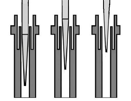 The spacing between the straight part of the needle and the needle jet determines the gasoline contributing to the idle mixture and the mixture before the needle taper comes into play. That "into play" happens when the slide is open about 1/4 the diameter of the bore (the carb size). So until that taper starts to raise above the needle jet then that spacing between the needle and its "jet" is the most important. If the engine runs too weak there then the needle needs to be skinnier or the jet hole needs to be wider. If running too rich then the needle needs to be wider or its jet needs to be skinnier. "Too rich" also happens due to that jet hole getting wallowed out with piston port intake engines or reed valve engines bigger than 150cc. Sometimes the oblong shape of the hole is visible to the naked eye if it's enough. In that case you need to buy and install a new needle jet or melt solder onto its interior and drill out a new hole (but of course this is the least favorite option but the only one for some old carbs). How To Test While riding, very slowly open the throttle. If the bike doesn't accelerate in proportion to the opening then the needle jetting is too lean. If the needle taper "kicks in" too late then you can try raising the needle by lowering the needle clip. If the bike is sputtering or with inconsistent exhaust barks and then runs fine when you crack the throttle open then it is too rich there. The tricky part of dealing with needles is finding an agree-able compromise for when the taper kicks in and how the engine runs mid throttle. If you are just racing it then only pay attention to how it runs mid throttle. Needle "Adjustments" With Keihin and some others you can choose different needle widths and/or different needle jets with different hole sizes. This "adjustment" affects how the engine runs at idle and off idle. Also available are needles with different taper angles. The more the taper angle, the richer the needle. Here is my page listing available needles: PAGE Max Power By Matching Combustion Flame Speed With RPM 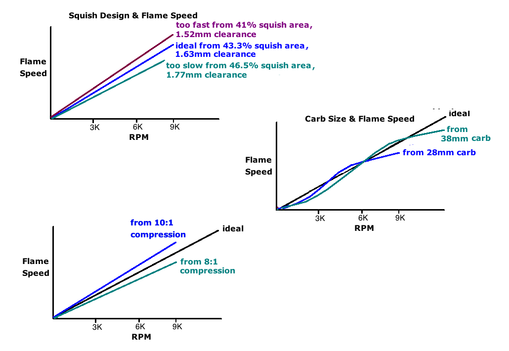 Three main factors affecting flame speed are carburetor size, engine compression, and squish band design. The bigger the carb, the higher the RPM before the atomization is best for high speed flame front speed. The higher the engine compression the higher the flame front speed. And both the squish velocity and squish volume has to be right to match the RPM and the height of the exhaust port. In this illustration the squish velocities are higher with smaller squish clearances. 9:1 is just a guess as being an ideal compression ratio because most motocross bikes are close to that ratio. Fuel Economy with Same Power I have two needle and jetting setups for my VM18 and I used the same method to jet both of them (main jet as rich as possible and still run good). One needle has a 1 degree taper and the other a 1.5 taper. So at WOT the 1 degree has more restricted flow area than with the 1.5 degree needle. That of course is compensated for by using a larger main jet. One way of looking at that flow area is by calling it a spray nozzle even though the flow is pulled up by vacuum. I theorized that the small area nozzle will create less large fuel droplets and more small ones. One research paper I read said that with more atomization the mixture seems richer (probably due to a more complete burn) and so can be made leaner without any power loss. Both setups gave me the same top speed going uphill and my jetting calculator showed that the small nozzle setup saved 7% gasoline use. This may also explain why smaller carbs give better fuel economy, because the higher air velocity atomizes the mixture more. How To Know If The Plugs Heat Range Is Correct I wasn't sure of the best way and so I emailed NGK and they responded and said that looking at how many threads are dark is the best way, with 3 of them being the ideal. I had started to use three original NGK plugs (bought from an authorized dealer, not the cheap copies from Amazon) that were #7, #8, and #9 heat range. I was also experimenting with two engine oils that were 2/3 synthetic and one that was all mineral oil. What I found was that the semi-synthetics showed that #8 was the correct one, which I had thought was correct all along, but that the mineral oil darkened too many threads on the #8 plug, not because I needed a colder higher numbered plug but because the mineral oil is less heat resistant than synthetic and so it only made it look like a #9 (colder) was needed. I am sure about this because I was doing specific test runs and then taking the head temperature at the end of each run. The mineral oil didn't cause a higher head temp and so a higher numbered plug was not needed. What is needed is for me to adopt this new idea that reading the ground electrode (just as valid) or the threads is different with oils that are fully or mostly mineral oil. Amalie SynPlus, which is a very good mineral oil, caused the ground electrode to show the color change to happen 3/4 of the way from its tip to where it connects to the plug body, and for 5 threads to be darkened. Oils that may also do the same because they are all mineral oil are Amalie Pro 2T, Yamalube 2R, Castrol Go!, PJ1 Goldfire Pro, BelRay Mineral Oil, Bel-Ray SL-2, Spectro Oils 2T, and Schaeffer 9000.  Reading the overall color instead Before doing this you need to make sure your carbs main jet is properly sized. If a plug is too cold (too high a NGK #) then the plug will be very dark with too much deposits on it due to the plug not getting hot enough to burn off the deposits. This can lead to the plug quickly fouling. If a plug is too hot (too low a NGK #) then the plug will be too light colored which means its getting too hot to allow deposits and so it may become hot enough to cause auto-ignition like a glow plug does. You know this happens when you press the kill button but the engine keeps running. This also raises the head and upper cylinder temperature and you know that high temps are your engines enemy because that can causes piston seizing. Switching Your Perspective Before we used to change the jetting to get a medium color of plug. But now we know that the overall color is affected also by the plug heat range and which engine oil is used. Now we jet for best power and use the plug color to know if the plug heat range is correct for the engine oil used. If you switch oil then you have to clean off the plug deposits, go riding, and then inspect the plug color to see if it is correct for that oil. |