|
And My Squish Calculator 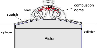  The squish band is one of the factors affecting engine power. Other factors: carb size, engine compression, and ignition timing. Squish Band Width The width affects the length of time of combustion. The air/fuel under the squish band burns later than the bulk of the mix in the dome. So the more mix is guarded there, the longer the combustion time. The wider the band, the longer the combustion duration. That duration needs to match the time duration between TDC and port opening which can be called the power stroke duration (PSD). POWER STROKE DURATION The higher the port and the higher the RPM, the shorter you need to make the combustion pressure duration with a skinnier squish band. If the combustion pressure duration (CPD) is too long then pressure is lost out the exhaust port which should of been used to push down the piston and rotate the crank. If CPD is too short then you have the bulk of the pressure happening when the angle between con rod and crank is not very good so less power contributes to crank rotation which lowers engine power. Squish Velocity The wider the squish band and smaller the squish clearance, the faster the squish velocity. It's been said that less than .6mm squish clearance messes with the needed boundary layer of air/fuel over the metal, so don't go less than that. Otherwise the only obstacle is to not have the velocity so high that it causes detonation or overly scatters the combustion flame which lowers power. 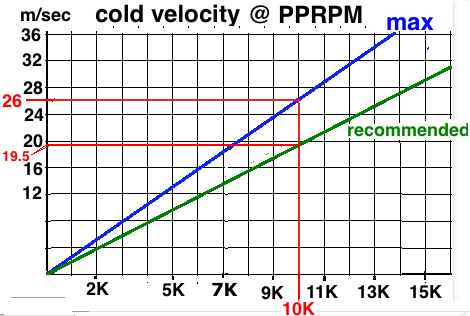 How To Test You can install a thicker head gasket to increase the squish clearance to also increase the squish volume but if that results in less power then you'll know your engine wanted a shorter combustion duration, not more, and so you can lathe down the head or cylinder mating surface as long as you don't reduce the squish clearance to less than .8mm. Needed Squish Band Width You need a squish velocity calculator to juggle the width, clearance, and velocity. But the main idea here is that the narrower the band, the less air/fuel is guarded under the squish band to burn later. Typical for high RPM / high duration exhaust port engines (over 180 duration) is 30% to 40% squish area. Typical for low RPM / low duration exhaust ports is around 45% to 55% squish area. Graph Analysis Below is a graph demonstrating what I believe happens with a wide squish band, how it lengthens the combustion to better match a low duration exhaust port. Notice how the narrow band graph lowers to 9% at 80*ATDC which matches a 200* exhaust port duration. And the wide squish band graph is at 9% at 90*ATDC which matches a 180* exhaust port duration. I didn't guess at the crank force graphs. I'm pretty good at math and I did lots of it to come up with those derived values from the PSI graph. So the idea is to match the combustion pressure duration with the power stroke duration. Long exhaust pressure time matches a long time from TDC to port opening. Adding all the numbers of the graphs it is revealed that the long duration graph gave 10% more total crank power. That happens because the more PSI exists at later crank degrees, the more power is transferred to the crank due to the angles involved between con rod and crank. 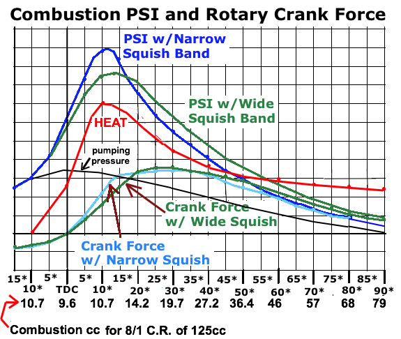 % Squish Area It's easy to find the % of bore area the squish band occupies. The main formula is Area = 3.14 x (diameter/2) x (diameter/2) So figure the center non-squished area and subtract it from the whole bore area. Then divide that result by the bore area. It will give the % as a fraction such as .45 which is 45%. Feedback From Others On This Subject: Luke V: "on a 125cc cvt engine I didn't get over 30hp, crs ICC cylinder. I talked with Helmut, a former TM Racing factory tuner, and he told me to make the squish band narrow, just like you see in the TM ICC engines. I did what he told me, first run 36 HP and with some fine tuning 39.7hp. All peak Powers were at 13k so that didn't change. 10 years back I did scooter racing engines. Somehow I always came to a narrow squish band thru testing. Engines ran 14.2k rpm and 20-25hp. Exhaust durations were always between 192 and 198." Me: "Luke, when you changed to a narrow band did the exhaust note soften? I'm thinking that with a long combustion pulse that there's more pressure when the exhaust port opens which would cause more exhaust noise." Luke: "engine sounded smoother" Max S: Click here for the story of his improving his NSR250. Michael W: "I have found the squish clearance is very much related to pipe temp. Looser squish is higher pipe temp/cooler piston. less risk. Tighter squish is cooler pipe and hotter piston. More risk." [the hotter piston is due to less squish volume to burn more gradually. Burning most everything right away in the head dome causes higher piston temps] Matching Squish Band to Piston For zero squish angle between piston and head the DIY way is to glue rough sandpaper to a piston top. Then insert the wrist pin and circlips and bend a thick wire (such as clothes hangar) around the wrist pin and twist the two wires together in a clockwise motion and stick that into a drill chuk and use the drill to rotate the piston while pressing it onto the squish band. That will make the head conform to the piston so you can reduce the clearance with less possibility of contact at WOT when the piston rises even higher due to extra heat expansion of the connecting rod. Guidelines Doing further study with my squish velocity calculator I'm finding how to choose the squish characteristics by the exhaust port duration and RPM of peak power. First it is best to try to get the lateral squish area % of bore correct. Then change the squish clearance to get the volume under the squish band at 5*ATDC correct. (On page 355 of Blair's 2 Stroke Design paper he wrote that the squish clearance volume is perhaps the most important factor.) The right graph was derived from my calculator with the squish clearance set for 75% of the velocities safe maximum. Use this formula to figure the time from TDC to exhaust port opening in milliseconds and then go by the chart below to the right. ms = ((360- exhaust duration) x 83) / peak power RPM. Here's how to calculate the squish area % of your cylinder head now: Subtract the inner dome area from the bore area and then divide that by the bore area. Area = 3.14 x (dia/2) x (dia/2) 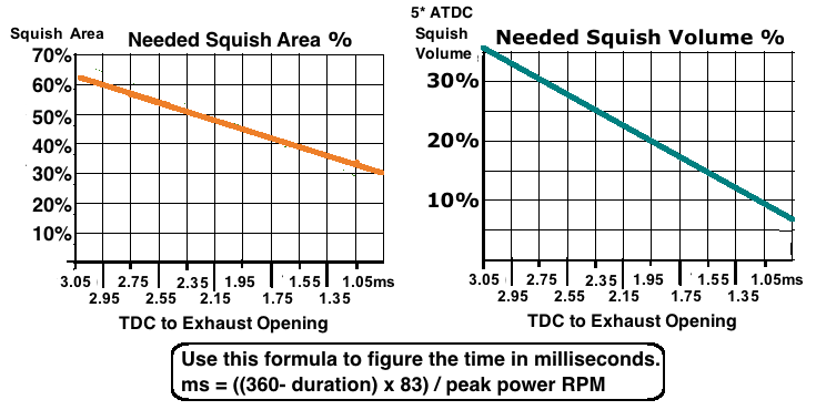 Squish Effects Here's an additional way of thinking about squish effects. The time till peak pressure is greatly influenced by the squish velocity, and the remaining pressure time is greatly influenced by the squish volume. 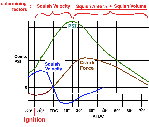 If you want help to perfect your cylinder heads squish band then just buy my Squish Velocity Calculator for $15. Squish Velocity Calculator This calculator is necessary to utilize the information on this page. Other calculators give different results. 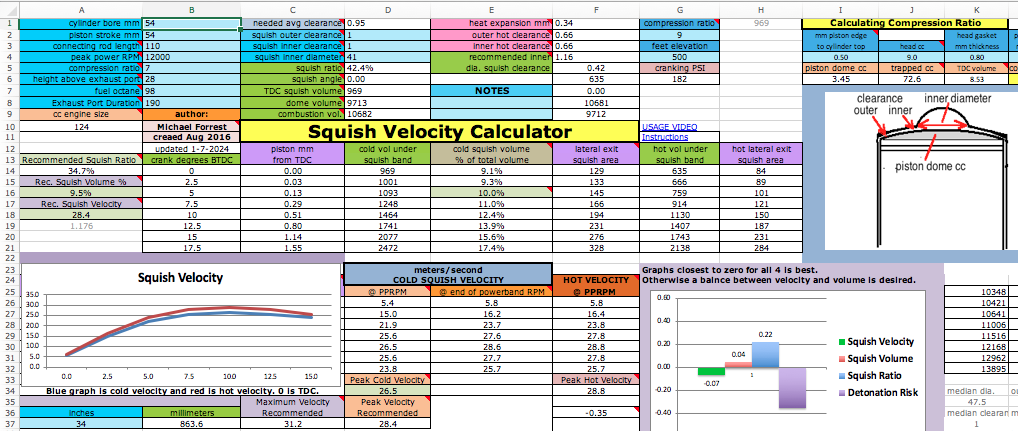 This
squish velocity calculator
is an Excel spreadsheet based on Gordon Blairs formulas. It shows the
velocity from 15 to 0
degrees BTDC. The peak velocity will usually be at 10 degrees.
All linear dimensions are in
millimeters. An inch to
millimeter converter is at the bottom left of the page. All entry boxes
are in light blue. Just click onto the entry box, type in the correct
value, and then hit the Enter key. Don’t enter any values in the white
boxes. Enter the cylinder bore (diameter) at B1 and the piston stroke
at B2. Go to
the hot rods
site
if you need to look up the length (center to center of its holes) of your
connecting rod for its entry at B3. (Otherwise just enter 2x the stroke.) If you've seen a horsepower/torque graph for your engine then enter at B4 the RPM that's of the peak power. Otherwise enter the RPM that you measure where the highest power is, or use the calculator at the bottom left of the spreadsheet to estimate that RPM based on exhaust port duration and pipe length. The
engine compression ratio at B5 is “trapped” which means it is the ratio
of
engine volume above the top of the exhaust port to the volume when the
piston is at TDC.
Next item down at B6 is the exhaust port height from the top of the
exhaust
port to the piston top edge at TDC. (example: there is 51mm from top of
cylinder to the top edge of exhaust port. The piston at TDC is .8mm
below the top of the cylinder. Port height would then be 51 minus .8 which
equals 50.2mm.) At D2 you will enter the value of the cold squish band
clearance (from piston to squish band at TDC) at the outer skirt of the
bore, and at D3 the cold clearance at the inner part of the squish
band. These values reduce when
the engine is hot and is shown at F2 and F3. That heat expansion amount (at F4) is
based on the expansion factors for steel (9.6) and
aluminum (13) and the rod length and bore diameter (because the pistons
pin
to top distance is usually around half that value). My 55cc engine has a cold
18m/s squish
velocity which is 22.3m/s when hot which is a significant change. But still everyone refers to the cold squish velocities so this calculator shows the cold values. The value
of squish band “inner diameter” is to be entered at D4. That is at the
juncture of the squish band and the head dome. Measure it right before
it starts
to curve upwards towards the dome. At D5 is the percent of the
squish area to the cylinder bore area. This is determined from the squish
inner diameter value listed above it. The column starting at D26 shows
the squish velocities at peak power RPM when engine is cold. The column starting at E26 shows the
squish velocities at top RPM. Those columns are both the "cold" values. After entering the data then compare the three recommended values to the calculated values. Both the volume and the velocity are important and since changing one changes the other then sometimes you have to strike a balance between the two calculated values if you don't want to modify your existing squish band. Both are affected by squish area (ratio) and clearance. 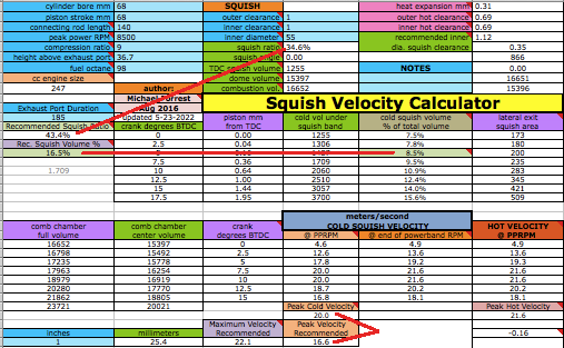 Gordon Blair recommended 15-20m/s cold squish velocity at the peak power RPM (but he didn't say for what RPM). (I think that was
“cold” because there's never been a calculator showing the hot values). To be able to stick to his
recommendations this calculator figures the velocity both for peak power and top RPM. As a test case we can look at the '89 Honda CR500 which had a detonation problem from too high a squish velocity. I was able to gather all the details but I had to assume a 2 degree squish angle. At 7% less than its peak 7700 RPM (7200) its cold velocity with a 2 degree angle was 23.6m/s and with Eric Gorrs fix of lessening the squish band from 18mm to 15mm the velocity became 19.3m/s. Since 2 degrees squish angle is the normal max I'm going to agree that Blairs 20m/s is the max before detonation for a big engine. Click here to
read up on this topic. Here's a report from a user of my squish velocity calculator: Chris H wrote: "The spreadsheet was very straight forward to use and understand. The main reason I needed it was to check what MSV we are currently running, as the engine is suffering from extreme detonation, even after retarding the ignition timing and richening up the jetting. This lead me to believe the MSV we are running may be too high. Your calculator told me the MSV was indeed around 36m/s hence we are in the process of reducing the squish band width and increasing the squish angle." [to reduce the velocity] Another Squish Calculator testimony: NP wrote: "The bike I am currently working on is my personal 2003 Honda CR250R, which is a bike that needs some help from factory specs. All factory heights and durations of the ports other than a thinner (2005) base gasket, and I have converted to a domed piston with an intake window. Getting the cylinder head correct for the changed piston is my main objective right now. [time passed] I have excellent news. I ended with .01 [1% over the ideal] squish velocity, .03 squish volume and -.01 squish ratio [on the bar graph]. I was even able to get spot on with 1.62mm squish. I removed a lot of material to get to the end goal. This resulted in a very nice power that pulled strong from low rpm to a much higher rpm that it previously didn't reach. The bike was exactly how I wanted it at this track. Very awesome power. Almost like there was no power band, but just consistently pulled from low rpm all the way through until it signed off. No dips or inconsistencies. I am very thankful for all of the information and for the hard work on the calculators!" 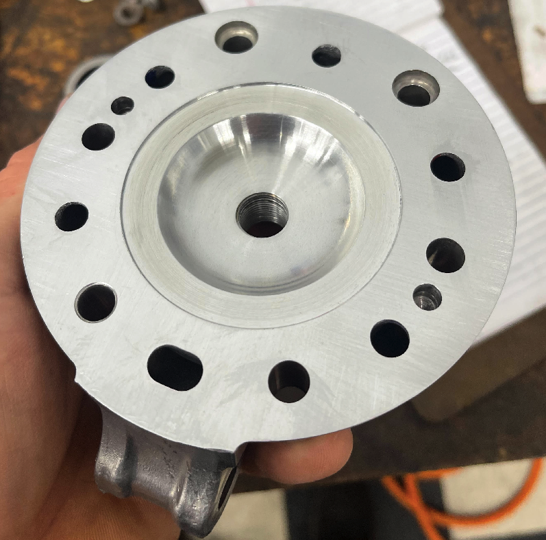 Click here for on-line usage instructions. Click here to see my video on the subject. You can email me at a57ngel@yahoo.com with any questions or just to chat. Check out my other 2 stroke calculators HOME |