Jetting Keihin carburetors
Below is a screenshot of my spreadsheet for Keihin carbs (PWK, PJ, PE). Below the instructions here are the needle and needle jet info that you will need to know such as the inner diameter of the needle jet of your carb. Here's how to use it: Enter data into all the light blue cells of the spreadsheet and the program will graph the jetting. If you hover the mouse pointer over a cell with a red corner then a message will pop up telling you about that cell. 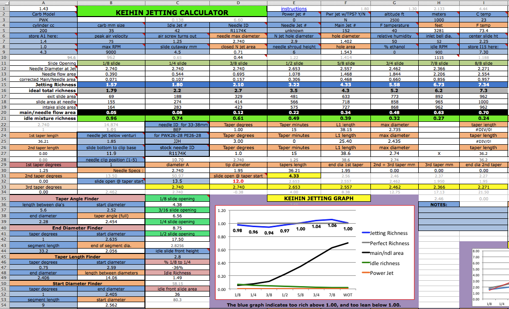 Here's the sequence to follow: 0) First make sure your real life idle jet size is correct. Turn in the slide stop screw till you have a slightly fast idle. Then slowly turn the air screw till you find where it idles the fastest, then readjust the slide stop for the same fast idle as before if it has changed. Then slowly turn clockwise the air screw till the idle speed starts to drop off due to starting to be too rich (but which is good for starting w/o the choke in warm weather). This should result to be within 1 to 2 turns out. If it is less than 1 turn then you need a bigger idle jet. If it is more than 2 turns then you need a smaller idle jet. Install correct idle jet if necessary and repeat procedure. Then turn the slide stop screw till you have a normal idle speed. The idle jet that gives the best starting and idling is the right one for use with this program and you can change it back later. Normally if you have to make the idle mixture too rich for idling in order to help compensate for weak throttle response as you crack the throttle open then you either have the needle clip in too high a position or you need a skinnier needle or fatter needle jet (the brass hole the needle slides into). 1) Make sure your main jet is correct. Click here to find out the best way to size the main jet. For small carbs you may need to lower the needle shroud if one main jet size is too rich and the next smaller size is too lean. In that case put in the rich jet and then lower the shroud .5mm (.02") at a time till the jetting is right. [Plug Reading] 2) Determining mid throttle needle-dependent jetting - Mark your throttle body and throttle grip so you can see where 1/2 throttle open is. Ride at a steady speed on a flat road, or on an inclined road if the bike wants to accelerate much at those settings. Then listen to the exhaust note. If it is irregular and/or sputters occassionally then the needle is too rich at that setting. If it runs fine but drops power when you quickly open the throttle then it is too lean there. Something between those two extremes is desirable. You need this info to be able to entr a jetting richness/leanness # at A8. To lean out the mid throttle jetting a bit you can lower the needle by repositioning the clip higher, or do the opposite to richen the mid throttle jetting. But be aware that the needle position also affects the transition of power off idle. If you have to lower it so much that it causes too much of a weak zone off idle then you should just buy a needle with less taper angle.
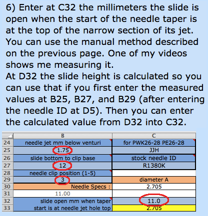
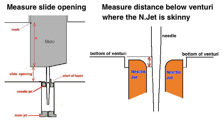
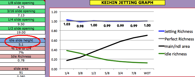
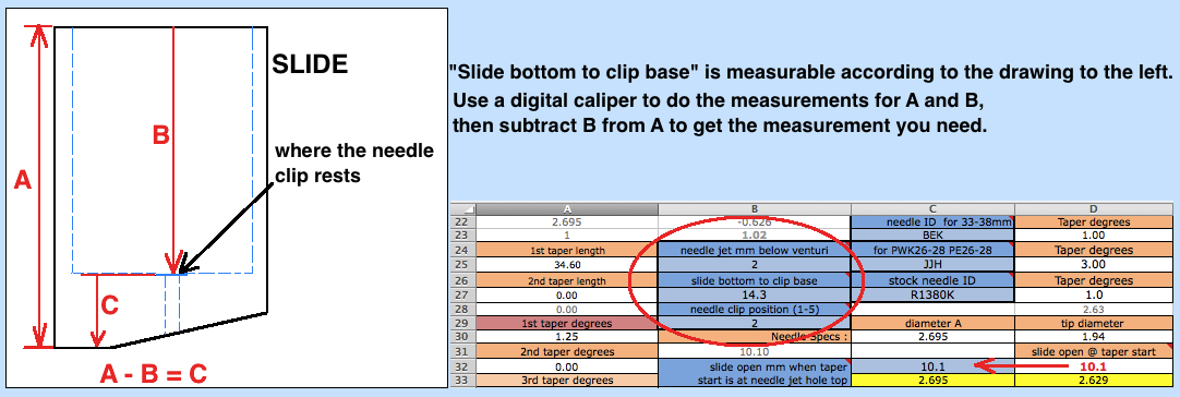
3) Go to the last sheet (click on the velocity tab at the bottom left of the screen) to find out the maximum air velocity to enter at B7 at the Keihin sheet. If you aren't sure of the transfers duration then enter 125-130 for race engines or 115-120 for street/trail engines. 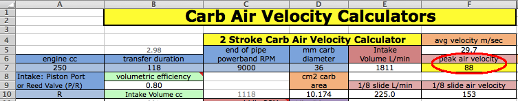 You'll need to set the slide stop screw for an even engine idle and then take the carb off and measure the idle slide height for C45 of the jetting sheet. The calculated value of 11% of the carb bore is at C14 of the Air Velocity sheet which is acceptable with reed valves. If you absolutely don't want to take the carb off to measure the slide opening then use this value. 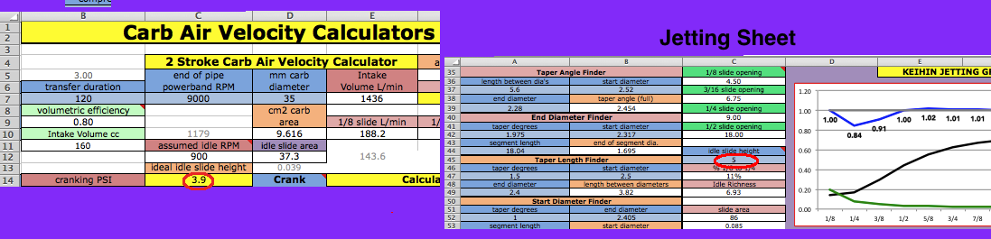 4) Look at the 3 needle types at section C23 to C27 and if you want to graph a needle that is within that group then enter its code and then enter the same needle code at D5. Or ignore the section from C23 to C27 and just enter at D5 a needle code for one of the needles listed from B56 to B105. Or enter the data for a custom needle starting at B107 and enter at D5 whatever you named it. For the 3 letter needles (ie: DEK) the 1st letter indicates the taper angle, the 2nd letter the L1 length, and the 3rd letter the maximum diameter. At the right side of the sheet you can see the code breakdown starting at the J column. For OEM needles (example: R1172J) the 1st pair of numbers is the taper angle, the 2nd pair of numbers the diameter, and the last letter the L1 length.  5) The needle jet (the hole that the needle fits in) diameter for E7 is 2.9mm for PWK33-39mm, PJ34-38mm, PE36, PWM38. And it's 2.6mm for PWK26-28mm, PE26-28, PE20-24. Enter the appropriate diameter at E7. 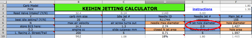
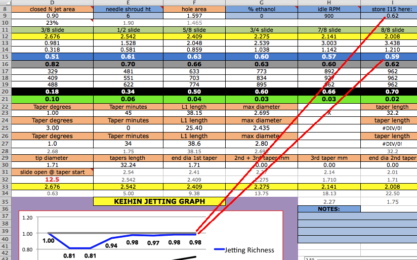
9) Now you can set the 5/8 slide position ideal graph value according to your own evaluation of mid throttle jetting. This completes the skeleton of the ideal graph which the program will fill in the remaining points for a complete graph for your jetting to be compared to. Hover your mouse pointer over A8 to read the lengthy comment stored there. It basically says that you need to enter 1.0 if the jetting there is perfect, or a higher # if jetting there is too rich, or less if the jetting there is too lean. Then enter the # at E28 at A9 which will set the gray graph mid point that all future changes will be compared to. After setting the three main points on the grey graph you need to leave them alone. All virtual changes will be to try to get the blue graph to be equal to the gray graph. To be the most precise in this step it iis best to remove the carb and open the throttle till the slide is 5/8 (62%) open and then mark the throttle and throttle body. (You can use White-Out) 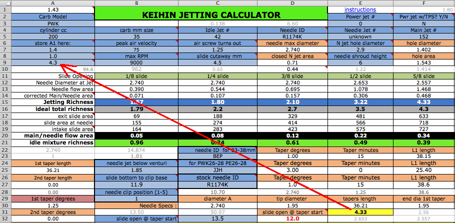
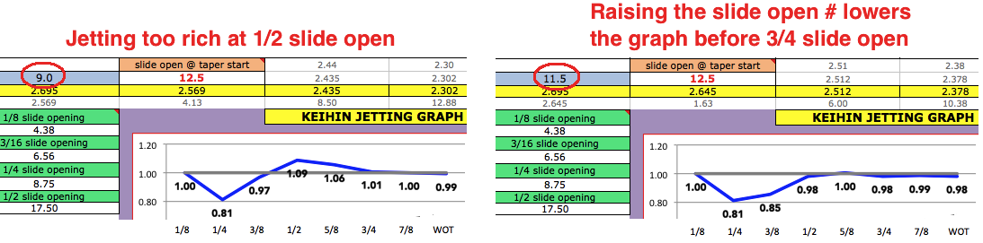
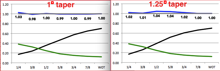 Multi-tapered needles are often too rich at 1/2 or 5/8 slide opening. If you feel that is the case then find a single taper needle to use. 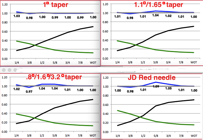
12) Re-record this spreadsheet with all of your data in it. For example, if saving data for a YZ250 then save it as JettingCalcYZ250.xlsx 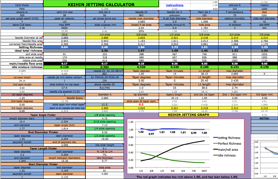 Keihin needle jet inner hole diameters 2.9mm for PWK33-39, PWM38, PJ34-38, PE36, FCR28-41 2.6mm for PE26-28, PWK26-28, PE20-24 Heres what PWKs are often equipped with: 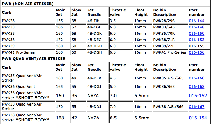 Needle Data for PJ34-38 PE35-38 PWK33-39 PWM38 from Jets R Us: The 48 series are for the large PWK carbs. The 46 series are for the smaller ones. This shows that you just use the last 3 letters of this code. 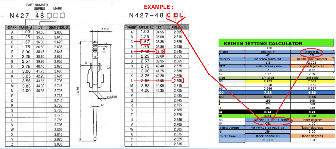 As an example look at the top left needle which is AEF. The first letter refers to the needle taper degrees/minutes, the second letter to the L1 length, the third letter to the diameter. So AEF has 1 degree 0 minutes (1.0 degrees), 38.15mm L1 distance, and 2.655mm needle diameter (at the straight section). CEJ has the degrees increased by 34 minutes (34/60=.57 degrees), same length, and diameter increased by .02mm for a leaner mixture at low throttle settings. 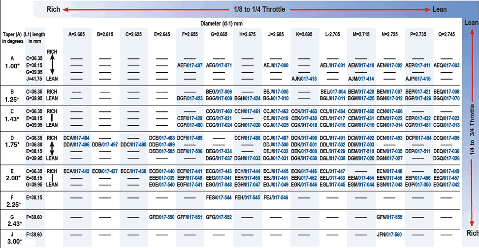    Here's Keihin's engineering drawing for the N3 series needles for the PWK33-39. They all have the same dual taper but vary in upper width. 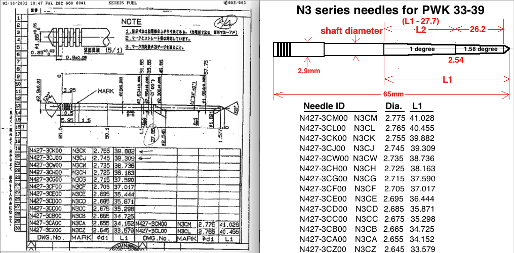 I just lately came across the N3C data and don't conveniently have the room to squeeze it into the program so I put it at the bottom of the spreadsheet (starting at row 183 although the calculator doesn't access that data) and you'll have to enter any of their data in as a custom needle at one of the rows from 107 to 111. For all other 65mm needles you can follow instructions at my video to find their specs to enter into this spreadsheet. 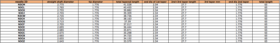
Analyzing the needle diameter graphs on the JD Jetting Spreadsheet I came up with these specs on the listed needles which are now programmed into the Keihin sheet on my jetting calculator. 
Needle Data for PE26-28 PWK26-28 from Jets R Us :  Needle Data for PE20-24 from Jets R Us : 
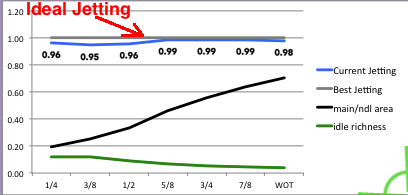
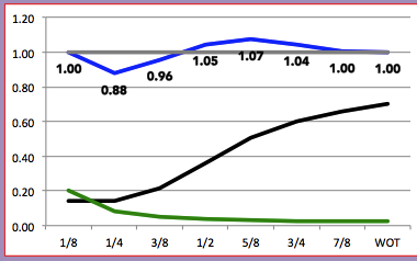
Keep in mind that the L1 length is not the length to the beginning of the taper but is the distance to where the taper will have a 2.515mm diameter. With needles that have a max diameter less than 2.515 then that L1 spot is actually imaginary, as if the taper kept extending upwards past the taper start. Needles with less than 2.515mm diameter: PE26-28, PWK26-28, and most needles for PE20-24mm. This was the explanation given to me by Jets-R-Us. Here's the needle code list for the rare needles for the PWK29: 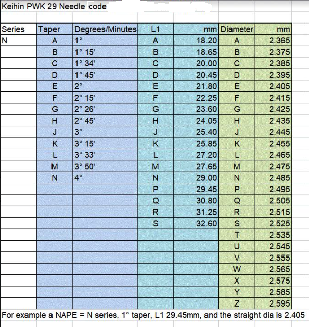 Main jets and needles are also available from Sudco which is a preferred source for genuine Keihin parts. Just look at the main menu and then type in the page # you want in the upper left hand corner. These needles are for carbs PWK33-39, PJ34-38, PE36, PWM38 : 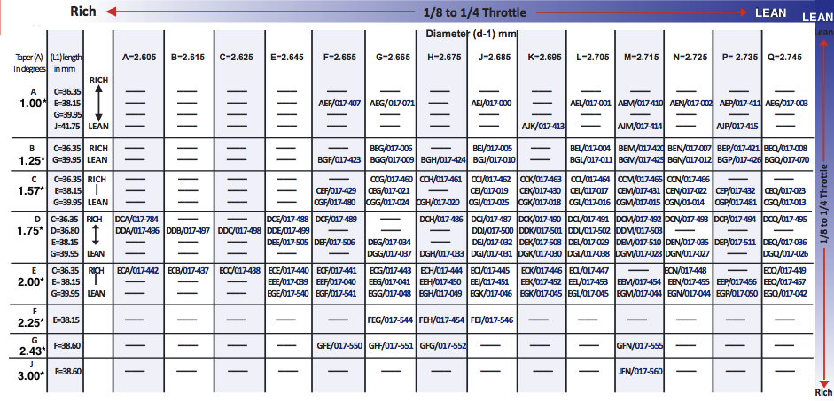 JD Needles 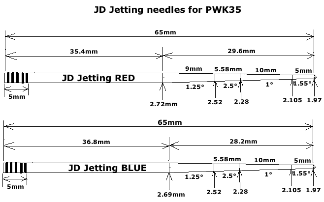 Supposedly the experts at JD Jetting sell a custom made needle that is supposed to be ideal for the PWK carbs. But a person just consulted with me for better jetting and he measured it all and I figured out its angles of its 4 tapers and when I plugged its specs into my jetting calculator the result was really rich up to 3/4 slide open. So I found a needle that SUDCO sells that will give him perfect jetting according to my calculator. What is ironic about this bitter tale is that the spreadsheet by JD Jetting is what I used many years ago to find a better needle for my '89 Honda CR250. It was a good program but it only compared needles so you had to be experienced enough to know what part of the needle needs to be fatter or skinnier. About a year ago I asked if he could share his needle data with me since he no longer sells his spreadsheet and he said no and then broke off communication with me. I thought that was pretty stinky but by using his calculator I was able to logically derive the needed specs from a slew of needles he had programmed into his spreadsheet. He could of been nice and just gave them to me but instead he made me work for hours to get them. So now I have the full story. Any way here are the jetting graphs. On them the grey line represents perfect jetting. 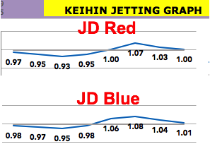
If you have any questions then just email me at a57ngel@yahoo.com |