|
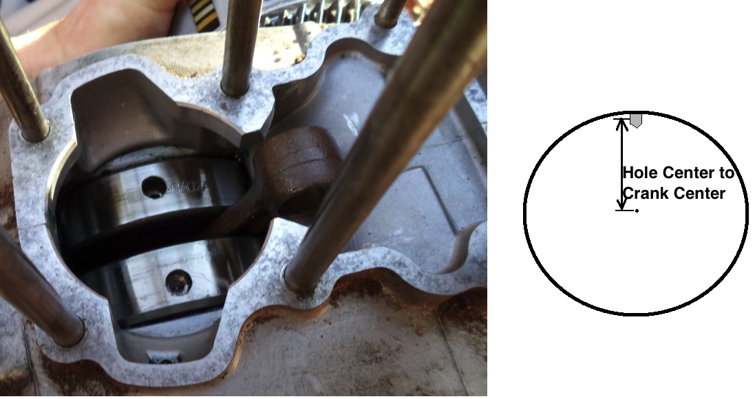
Here's the Excel file screenshot. All the light blue boxes (cells) are where you enter the needed info. The info for my 48cc crank is in there as an example. You can refer to my video on how to figure out equivalent balance holes for cranks with metal removed around the con rod pin area instead of holes. You will need a digital food scale and digital caliper. You can buy a scale at Amazon for $19 or one at WalMart for less. WalMart sells a digital caliper for $19 or you can buy one from Amazon for $23. This screenshot shows my engine which has a top RPM of 6900 so I need to lighten the wrist pin to cause the 1.0 RPM to be at least that high.  Notice the usage instructions starting at C44. First, enter all the necessary data in the light blue cells, enter the highest RPM of your engine at E2, and click the "Graph V/H Forces" macro button to the right of the crank photo to display the vibratory forces throughout the RPM range in the graph starting at F1 (This isn't essential if your spreadsheet program can't use macros. In that case just type in the RPM you want to know about into E3, usually your top RPM. It's balance value will display at E45.) Then adjust the counter balance hole sizes (or add more holes or fill in holes) till the # at E45 is close to 1.0 at your top RPM. If it's more than 1.0 then increase the size of the holes close to the lower conrod pin. The value at E45 changes as you enter different hole info. If you are measuring where the current balance holes are and you want to calculate what the angle is between the hole and where the center of the con rod pin is then just measure the radius and the chord according to the picture below and use the angle calculator below K46 on the spreadsheet. 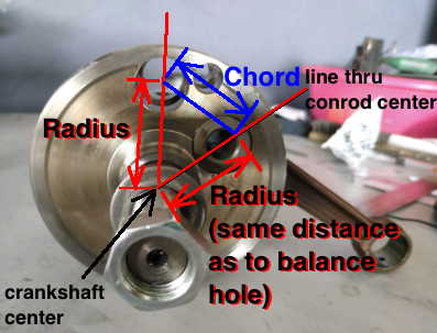 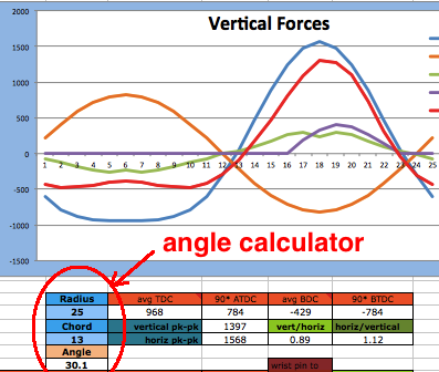 Any of four "hole sets" can be two or four holes each. If only two holes, they need to be at 0 or 180 degrees, aligned with the conrod pin. The example on the spreadsheet shows four holes 24.5 degrees from the conrod pin (set #1), two holes in line with the conrod pin (0 degrees, set #2), 2 holes opposite the conrod pin (180 degrees, set #3) drilled in from the exterior not the side, and two holes in line with the conrod pin (0 degrees, set #4) drilled in from the exterior not the side. The "filler" of holes can be any of the five things listed at A29 to C29 and B30 and C30 (air, ABS plastic, aluminum, brass, lead). Filler #6 is anything of your choosing. Just find its density online and then enter it at D30 with ".00" before it. The example here is beryllium copper with a density of 8175 which I entered as .008175. The hole filler # (1-6) is to be entered at row 33. Some people like to fill holes to not lose any crankcase compression. Or if the setup is over-balanced then holes can be filled with steel or lead to correct that. I wouldn't fill a hole just for concern about crankcase compression because that affects engine power very little. 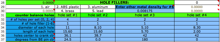 The remaining necessary data is the length of the holes (usually same as the width of the crank wheel), the distance from the hole center to the center of the crankshaft, and the degrees of the holes from the vertical (which goes through the conrod pin). Most holes are close to the con rod pin but if the holes are too big then you can counter that by having two holes at 180 degrees which would be on the opposite side of the crank than the con rod pin. If the ends of the con rod has oil holes or slots in it then you can add that info starting at H141. 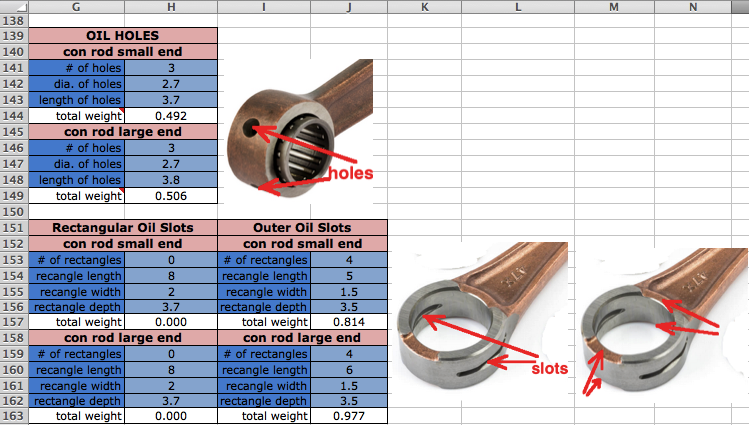
For most engines the main goal is to have the # at E45 at top RPM under 1.0. The max engine RPM at E2 is the maximum RPM that you normally use. If you decide to drill holes into the outer part of the crank wheels, then to know how to account for the area of the drill bit tip/cone just divide the mm width of the bit by 10 and use that as the additional depth in the program, added to the depth of the shank. The "hole center to crank center" of row 36 is to be measured as shown in the drawing below. Measure to the middle depth of the shank. If you drill these holes then you have to do something to prevent any metal bits going down in the crank. It helps to use a magnet to accumulate the metal after drilling. Grind an X into the crank wheels with a rotary tool and cutting disk where you want each hole. That keeps the drill bit from wandering. You can start with a smaller carbide drill bit and then drill larger.
 To change millimeters to inches just divide by 25.4, so that as an example 8.7mm divided by 25.4 is .342 inch which can then be translated to 16ths of an inch by multiplying by 16 which gives 5.5 which isn't a whole # so it has to be converted to 32nds which is 11/32" (multiplying both numbers by 2). So a 11/32" drill bit would work to drill a 8.7mm hole. Questions about each bit of data to be entered can often be answered by hovering the pointer over the description box. That will reveal the note I have saved that explains more. But if you still have questions after reviewing this page then contact me at 19jaguar75@gmail.com Here is a compete description of what is required for each data entry cell of the spreadsheet.
Here's my YouTube videos about crank balance: #1 #2 #3 #4 The last video explains how to figure out the equivalent balance holes for a crank with sculpted out areas instead of balance holes. The method and the graph is different in the video because that was made before my latest update but still it is worth watching. Some engines also have an extra balancer shaft which reduces the average radial force on the crankshaft by 50%. Here's two pictures of one: 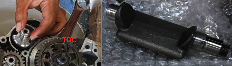 Their weight being spread out reduces the outward force from what you could calculate it being if all of its weight contributed to the central outward force. I figured the % contributing to that force is 55% of the balancer weight (excluding the end pivots). That is what shows at E152. On the spreadsheet starting at row 141 is this section which is needed to help you find the center of gravity of the balancer and its weight. First you should weigh the whole thing and then find the weight of its end shafts. Put water into a cup that is level with the top when the shaft end is submersed. Use the skinniest cup available. 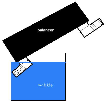 Then remove the shaft and measure how far down the water level now is. Enter the vessel inner diameter at E159 and the height change of the water at E161. The balancer weight without end shafts at E152 should be entered at E26. (Make sure E26 is 0 when working with a crank without an extra balance shaft.) 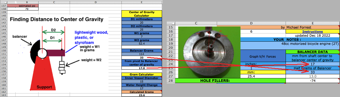 You'll need to glue something to the balancers flat surface which will extend away from it so you can hang a weight from it. Before glueing or taping the extender on then weigh it and enter its weight at E146. After it is attached then measure the two distances D1 and D2 to be entered at E142 and E144. Then add weights to the string/wire till the shaft will stay still without turning. Enter that weight in grams at E148. The calculated distance from shaft center to balancers center of gravity will appear at E155 which needs to be entered at E24. Below are radial force graphs, the first one being without a balancer. A balancer brings down the peak radial force and the difference between peaks. So when analyzing for a crank with extra balancer you can only go by the graphs, not by the number at E46 and the Vector Ratio graph which happens after clicking the macro button. Mostly go by the 360 degree forces graph. 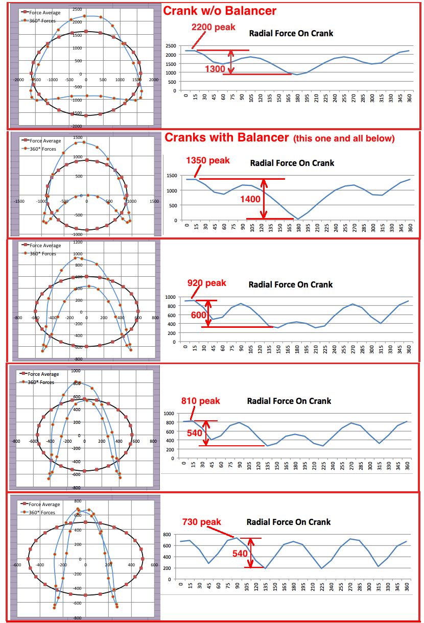 Most typically the balancers are set up like this : 
Cell Comments in the spreadsheet $D$1 Enter 2 for 2 stroke or 4 for 4 stroke $A$2 wrist pin diameter $A$3 con rod length from hole center to hole center $D$3 Set it to any RPM you want to see how the 360 degree graph looks like and see what the vector ratio is at E43. $AT$3 crank rotations per second $A$4 naked- without bearings $D$4 compression ratio of trapped volume above exhaust port. $F$4 cc area of piston top $A$5 including rings + bearing but without wrist pin $D$5 Riding area elevation which is used in the formula for cranking PSI. $E$6 cranking PSI when rings are good. $P$6 difference between the highest and lowest force $A$7 piston assembly, wrist pin, con rod end (B27) $D$9 bearing length in millimeters which is close to the width of the conrod section. $D$10 up to 125cc is usually 2-3mm, 250cc is 3.5mm, 500cc is 4mm $A$11 con rod small end race inner diameter $A$12 side to side width of section that encompasses bearing $A$13 thickness of con rod metal that encompasses bearing $AK$13 This lowers the combustions downward force on the frame because most of the force is translated to rotary momentum in the crank wheels $A$14 inner diameter of hole at large bearing end $A$15 side to side width of section that encompassses bearing. Add in the thrust washers if there are any $E$15 email: a57ngel@yahoo.com $F$15 Conrod big end force minus counter balance holes force. $A$16 thickness of con rod metal that encompasses bearing $A$17 outer diameter of pin $E$17 Updated June 13 2018 to include combustion force. Updated Jan 8 2021 to allow a different crank metal density at C43. Updated formula at E155 on Jan 14. Corrected balancer shaft calculation May 24 2021. Revised main formula March 2025. $F$17 combustion force on crank center that contributes to vibration $A$18 length of large con rod pin $A$19 Big end pin hole diameter. This refers to the pins center hole which is necessary to lighten it up. $E$21 This is for the data of an extra balancer shaft rotating opposite the crank. Its weight is downward when piston is at TDC. $A$22 estimated grams of section that encompasses bearing $E$22 See calculator at bottom of this sheet. $A$23 Use the calculator at E8-10 if you can't measure its weight $A$24 one crank wheel only, at big end pin Sheet1 $E$24 Distance from center of gravity of balancer to center of its shaft. $A$25 the net weight at the con rod pin area including the end of the con rod that encompasses bearing $A$26 centrifugal pound force due to grams at B25 $E$26 Weight in grams of balancer without end shafts. $A$27 estimated weight of section encompassing bearing $D$29 Click onto D12 for the web site with densities for all metals and then multiply by .001 before entering it at D30. (Just move the decimal point three places to the left.) This is for if you want to fill a hole with anything other than air, plastic, aluminum, brass, or lead. For instance magnesium is listed as 1.7 but you should enter .0017 $A$32 0 cancels out all data below it in that column. 2 is only for when the hole is in alignment with the conrod pin, either 0 degrees or 180 degrees (on the opposite side). 4 is the typical setup of 2 holes for each crank wheel that are equal to each other in distance from the crank center and degrees from the conrod pin and diameter and depth. $A$33 Refer to A29 to D30 $A$36 distance from center of hole to center of crankshaft $A$37 In the example picture the big holes are 25 degrees off from the pin. 0 is aligned with the big end pin, and 180 is at the opposite location. You can put holes at 180 when the balance holes are too big. $A$38 for both halves $A$39 meters per second velocity $C$42 Enter a different crank metal density if .00785 (for iron) isn't correct. $D$42 This is the density the program will use if you don't enter something different at C43. $E$42 Ratio of radial forces of the top 60 degrees of crank rotation to the second set of 60* from 105 to 175 degrees. $A$43 weight hanging from con rod to keep the crank from turning $A$45 This is just here to show you that balance factor changes greatly with each engine and is not to be considered a method for crank balancing since picking the right factor is just a guessing game. $E$45 This will be 1.0 at the smoothest RPM. See the top V/H graph to see where it crosses the 1.0 line. See note at D46 also. $A$46 Static balance weight divided by piston assy + pin weight with conrod small end weight $C$46 The engine feels the smoothest from 1.02 to 0.99. You can set the "smooth zone" to be at a lower RPM range by changing the top RPM at E2 to be the end RPM of your "smooth zone", whatever that may be. You can set it to be the RPM range that you most often ride in. If the graph never gets below 0.99 then the balance holes are too big and you either need a heavier piston assembly or new holes 180 degrees from the conrod pin. $L$46 average from 60BTDC to 60ATDC $N$46 average from 135ATDC to 135BTDC $A$53 angle from vertical $A$54 from the center of its arc if continued to make a circle $A$59 upward centrifugal force at TDC $A$64 the center of its arc if continued to make a circle $A$69 upward centrifugal force at TDC $A$74 the center of its arc if continued to make a circle $A$79 upward centrifugal force at TDC $A$84 the center of its arc if continued to make a circle $A$89 upward centrifugal force at TDC $A$97 the center of its arc if continued to make a circle $A$102 upward centrifugal force at TDC $A$107 the center of its arc if continued to make a circle $A$112 upward centrifugal force at TDC $A$117 the center of its arc if continued to make a circle $A$122 upward centrifugal force at TDC $A$127 the center of its arc if continued to make a circle $A$132 upward centrifugal force at TDC $F$135 total vertical force $G$144 This calculation will be used in the calculation at B27. $G$149 This calculation will be used in the calculation at B22. $E$150 Weight after subtracting the grams of the end shafts $E$153 Enter this value at E36 $E$158 The diameter in millimeters. $E$160 The height change of the water in millimeters. $E$162 This assumes the main metal is iron. HOME |